- ページ 8
GPS Fleet Management MLT-400iのPDF インストレーション・マニュアルをオンラインで閲覧またはダウンロードできます。Fleet Management MLT-400i 14 ページ。
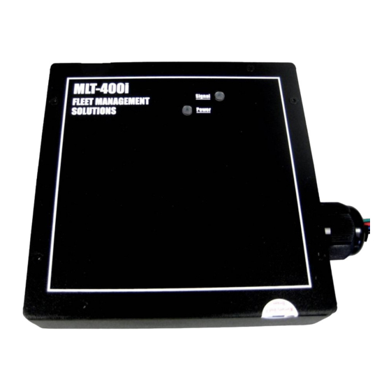
MLT-400i Installation Guide
MLT-400i/400iO I/O Connection
Note, when installing the modem, leaving easy access to the serial cable will facilitate any
code updates.
If additional I/O connections are desired for analog/digital inputs or digital outputs, the wire
harness is defined below.
MLT-400i Wire Harness Description
Wire Color
Use
Red
*
Constant power source. Not accessory power.
Black
*
Chassis Ground
Green
*
True Ignition Source
Purple
*
Signal Ground. Connect at analog sensor's ground.
Orange
*
Analog/Digital IN # 0
Brown
*
Analog/Digital IN # 1
Grey
*
Analog/Digital IN # 2
Blue
*
Digital IN
Yellow
*
Digital OUT # 1
White
*
Digital OUT # 2
Notes:
Cap Off any sensors not being used.
4
Securing the Unit
1. Before securing the unit, typically under the dashboard, record the IMEI/Serial Number
(ESN), Vehicle Name (Asset Name), Odometer and if available Engine Hours on the
Installation Checklist in Appendix B.
2. Use tie-wraps to mount the unit securely to a stable bracket.
3. If possible, orient the unit so the LED indicators are visible.
4. Do not place the unit near moving parts, or next to any of the vehicle's pedals
5. Loosely bundle any excess antenna cable, power wiring and unused I/O signals
6. Leaving easy access to the 9-pin serial cable will allow for code updating.
11/18/2009
# 0
FMS MLT-400i Installation Guide 4.3
Securing the Unit
Operating Range
9-30VDC
Ground
9-30VDC
Ground
0-5VDC
0-5VDC
0-5VDC
3-30VDC
12VDC, 50mA
12VDC, 50mA
8