- ページ 6
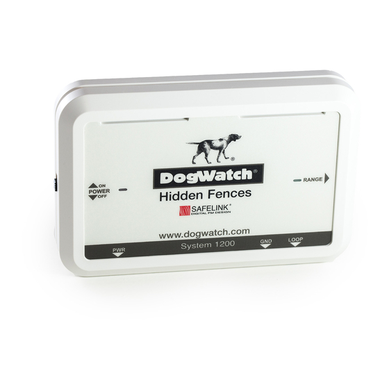
ペットケア製品 DogWatch System 1200のPDF インストレーション・マニュアルをオンラインで閲覧またはダウンロードできます。DogWatch System 1200 10 ページ。 System
DogWatch System 1200 にも: 取扱説明書 (16 ページ), オーナーズマニュアル (12 ページ), 取扱説明書 (9 ページ)

INSTALLING
1. Determine where you want the inside edge of the signal field to be and mark it with your training
flags. Flags should be 10ft apart. They mark the edge of the signal field and act as a visual aid
for both you and your dog during training.
2. The wire can be buried by cutting a 3 to 4" deep narrow groove using a spade or lawn edger.
The wire can also be clipped to fences, walls etc or passed through hedges or even loose laid on
the ground.
3. Place the boundary wire in the groove and cover it completely.
4. Join each end of the twisted wire to the each end of the boundary wire using the yellow
connectors (see diagram at back for use).
5. When crossing driveways, paths etc tarmac and concrete should have a ½" deep cut made
across them with an angle grinder the cable laid in the cut and sealed with a suitable sealant. For
gravel drives lay the wire inside a hose pipe and bury 4" down.
6. Testing: Turn the power switch on the red power light will come one and the green loop light will
be on and constant. PLEASE NOTE: in the video supplied the green loop light is flashing,
since making this video DogWatch have added a software upgrade and the loop light no
longer flashes.
7. Test the radio signal by carrying the receiver collar with the test light towards the boundary wire -
repeat this several times around the boundary. From Jan 2012 the test lamp and the collar
wrench has been combined into one unit. The image below shows the new tester (as shown in
your handbook) but the DVD currently show the old style (torpedo test lamp).
Diagram to illustrate placing the tester over the
probes (this is the same for the R12 & R12m
receivers)
