- ページ 8
コントロールユニット Cytron Maker Uno PlusのPDF ユーザーマニュアルをオンラインで閲覧またはダウンロードできます。Cytron Maker Uno Plus 16 ページ。
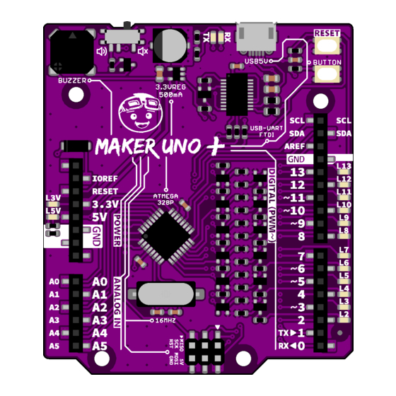
4. BOARD LAYOUT
LABEL
ON BOARD PIEZO BUZZER
A
Piezo buzzer is connected to pin 8 through slide switch (labeled B).
PIEZO BUZZER SLIDE SWITCH
Slide switch to connect between pin 8 to piezo buzzer (labeled A). To use piezo buzzer,
B
slide the switch on and program the buzzer. To use pin 8 for other purpose, slide the
switch off.
VOLTAGE REGULATOR 3.3V
C
Voltage regulator 3.3V used to regulate 5V USB to 3.3V and connected to pin 3.3V
(labeled I).
LED INDICATOR FOR USB-SERIAL
D
Indicates USB-Serial data for uploading process or debug purpose (Serial Monitor).
USB MICRO B CONNECTOR
E
Main supply for Maker Uno. Used for program and debug purpose (Serial Monitor) too.
USB-SERIAL IC CONVERTER (FT231X)
F
Converts USB data to serial data. Used for program and debug purpose (Serial Monitor).
RESET BUTTON
G
Button to restart Maker UNO program.
PROGRAMMABLE BUTTON
H
This button is connected to pin 2 and GND. To use it, user need to configure it as
INPUT_PULLUP.
ARDUINO UNO R3 STANDARD FEMALE PIN HEADER
I
Maker UNO female header pin follows Arduino UNO R3 standard. The only difference is,
Created by C ytron Technologies Sdn Bhd – All Rights Reserved
Product User's Manual -
FUNCTION
ROBOT.HEAD to TOE
M AKER-UNO-PLUS
Back to
I NDEX
7