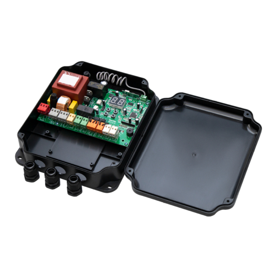
DoorHan PCB-SW 프로그래밍 지침 매뉴얼 - 페이지 10
{카테고리_이름} DoorHan PCB-SW에 대한 프로그래밍 지침 매뉴얼을 온라인으로 검색하거나 PDF를 다운로드하세요. DoorHan PCB-SW 20 페이지. Control board
DoorHan PCB-SW에 대해서도 마찬가지입니다: 프로그래밍 지침 매뉴얼 (20 페이지)

1. ELECTRICAL CONNECTIONS
WARNING!
The cable wires shall be protected from contact with any rough and sharp details. Before attempting any work on the
control board (connections, maintenance), always turn off power.
1.1. CONTROL UNIT WIRING DIAGRAM
5 А
PE N L
E N L
220-240 V
50 Hz
1.2. CONTROL UNIT TERMINALS
1. Power input connectors (J1 terminal block)
~220–240 V. PE, N, L — power supply connectors.
PE — ground terminal
N
power (neutral)
—
L
power (line)
—
2. Electric motors and signal lamp connectors (J7 terminal block):
1-2-3. M1 (COM/OP/CL terminals) — connector for the first electric motor. It can be used for opening of one leaf (if a pass
door or one-leaf gate is automated).
4-5-6. M2 (COM/OP/CL terminals) — connector for the second electric motor. It cannot be used for opening of one leaf.
7-8. LAMP — output for signal lamp connection (230V~ 40 W max).
3. Connectors for accessories (J4 terminal block (9—19 terminals) and J3 terminal block (20—21 terminals))
9-10. S-B-S — «Full opening» command: closing the contacts of the device connected to these terminals results in total open-
ing and/or closing of two gate leaves.
To install several devices connect their NO contacts in parallel.
11-12. PED — «Pedestrian passage» or «Close» command: closing the contacts of the device connected to these terminals
results in step-by-step opening or closing of one gate leaf.
10
0,8 А
Transformer
M1
M2
COM OP CL
COM OP CL
COM OP CL
COM OP CL
LAMP S-B-S
LAMP S-B-S
1 2 3 4 5 6 7 8 9 10 11
1 2 3 4 5 6 7 8 9 10 11
COM
COM
М1
М2
R
P
FOTO
FOTO
PED OP CL COM STOP +24V
PED OP CL COM STOP +24V
12
12
13 14 15 16 17 18 19 20 21
13 14 15 16 17 18 19 20 21
NC
(Normally
closed)
NO NC
NO NC
Key-button
ELECTRICAL CONNECTIONS
+
-
S Lock
S
Photocells
I
R
2
3
GND
2
1
COM
COM
3
GND
4
2
VCC
VCC
+24
5
+
+24
