DoorHan PCB-SW 24 프로그래밍 지침 매뉴얼 - 페이지 15
{카테고리_이름} DoorHan PCB-SW 24에 대한 프로그래밍 지침 매뉴얼을 온라인으로 검색하거나 PDF를 다운로드하세요. DoorHan PCB-SW 24 20 페이지.
2. OPERATION LOGIC
2.1. CONTROL COMMANDS
Control commands are sent by the connected devices to the corresponding terminals or by outer radio signals. Operation logic
of the automatic devices depends on advanced menu setting (see table 3.2).
By default:
START command — step-by-step door control logic (two door leaves): opening — stop — closing.
PEDESTRIAN command — step-by-step pedestrian passage control logic (one door leaf): opening — stop — closing.
STOP command — stop of door movement.
OUT(n) — universal output control, where n is an output number.
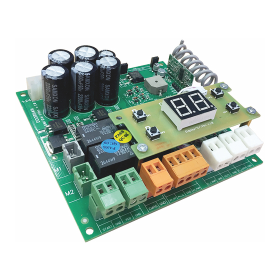
2.2. DISPLAY INDICATION
The display consists of two eight-segment indicators. They indicate commutation of control board terminals and the state of the
door, which the board controls.
Indicator
0
1
2.3 SLEEP MODE
The control board switches to a sleep mode to save energy. If there are no commands for two minutes, the program turns off the
display indication and power to photocells.
Pressing any control button on the board or giving control commands in sleep mode switches the control board to operation
mode and executes a control command.
NOTE.
Display indication and photocell power supply are turned off in sleep mode.
Segment
0
1
2
3
4
5
6
7
0
1
2
3
4
5
6
7
Description
Lights up when the door is opening
Not used
Not used
Lights up when the door is closing
Not used
Not used
Lights up when the door is stopped
Not used
Lights up when PH_OP contact is closed
Lights up when the door is open
Lights up when the door is closed
Lights up when PH_CL contact is closed
Lights up when PED contact is closed
Lights up when START contact is closed
Lights up when EMRG contact is closed
Lights up when radio signals are transmitted by remote controls
OPERATION LOGIC
Table 2.1. Display state
15