Asus Z97I-PLUS 매뉴얼 - 페이지 31
{카테고리_이름} Asus Z97I-PLUS에 대한 매뉴얼을 온라인으로 검색하거나 PDF를 다운로드하세요. Asus Z97I-PLUS 46 페이지.

5.
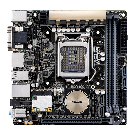
CPU and chassis fan connectors (4-pin CPU_FAN; 4-pin CHA_FAN1/2)
Connect the fan cables to the fan connectors on the motherboard, ensuring that the
black wire of each cable matches the ground pin of the connector.
Z97I-PLUS Fan connectors
inside the system may damage the motherboard components. These are not jumpers!
Do not place jumper caps on the fan connectors!
Advanced Mode > Monitor > CPU Q-Fan Control item in BIOS.
PWM, go to Advanced Mode > Monitor > Chassis Fan 1/2 Q-Fan Control items in
BIOS.
6.
Speaker connector (4- pin SPEAKER)
This 4-pin connector is for the chassis-mounted system warning speaker. The speaker
allows you to hear system beeps and warnings.
Z97I-PLUS Speaker out connector
ASUS Z97I-PLUS
CHA_FAN1
GND
CHA FAN PWR
CHA FAN IN
+5V
CHA_FAN2
GND
CHA FAN PWR
CHA FAN IN
+5V
CPU_FAN
GND
CPU FAN PWR
CPU FAN IN
CPU FAN PWM
SPEAKER
Speaker Out
GND
GND
+5V
PIN 1
1-17
