Baumer PMG10P 운영 매뉴얼 - 페이지 2
{카테고리_이름} Baumer PMG10P에 대한 운영 매뉴얼을 온라인으로 검색하거나 PDF를 다운로드하세요. Baumer PMG10P 40 페이지. Absolute encoder
Baumer PMG10P에 대해서도 마찬가지입니다: 설치 및 작동 지침 (32 페이지), 설치 및 작동 지침 (36 페이지), 설치 및 작동 지침 (32 페이지), 운영 매뉴얼 (44 페이지), 운영 매뉴얼 (44 페이지), 운영 매뉴얼 (40 페이지), 운영 매뉴얼 (40 페이지), 운영 매뉴얼 (36 페이지)
List of contents
List of contents
1 About this document...................................................................................................................................
1.1
Purpose ..............................................................................................................................................
1.2
Warnings in this manual .....................................................................................................................
1.3
Labels in this manual ..........................................................................................................................
1.4
Disclaimer ...........................................................................................................................................
1.5
Scope of delivery ................................................................................................................................
1.6
Name plate .........................................................................................................................................
1.7
Maintenance and service life ..............................................................................................................
1.8
Approvals and warranty ......................................................................................................................
1.9
Temperature range for operation and storage....................................................................................
2 General information ....................................................................................................................................
3 Transport and storage ................................................................................................................................
3.1
Transport ............................................................................................................................................
3.2
Delivery inspection..............................................................................................................................
3.3
Storage ...............................................................................................................................................
4 Description...................................................................................................................................................
4.1
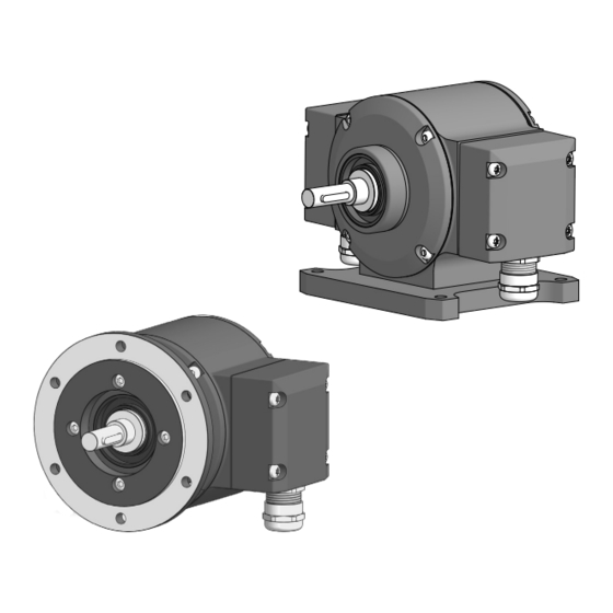
Rotary encoder ...................................................................................................................................
4.2
Required tools.....................................................................................................................................
5 Installation.................................................................................................................................................... 10
5.1
Mounting with EURO flange B10 ........................................................................................................ 10
5.1.1
Attach coupling onto encoder shaft....................................................................................... 10
5.1.2
Mounting encoder onto drive shaft........................................................................................ 12
5.2
Mounting with base B3 ....................................................................................................................... 14
5.2.1
Attach coupling onto encoder shaft....................................................................................... 14
5.2.2
Mounting encoder onto drive shaft........................................................................................ 15
5.3
washer ................................................................................................................................................
5.4
Notes when using a claw coupling (e.g. ROTEX®) ............................................................................ 18
6 Electrical installation................................................................................................................................... 19
6.1
CANopen®.......................................................................................................................................... 19
6.1.1
CANopen® features.............................................................................................................. 19
6.1.2
Connecting the CANopen® cable ......................................................................................... 20
6.1.3
Pin assignment CANopen® .................................................................................................. 22
6.1.3.1
6.1.3.2
6.1.4
CANopen® Terminal box ...................................................................................................... 23
6.1.5
Setting the terminating resistor ............................................................................................. 24
6.1.6
Setting the bus user address ................................................................................................ 24
6.1.7
Setting the transmission rate ................................................................................................ 24
ii
Mating connector (5-pin, A-coded) ................................................................... 22
Mating connector (5-contact, A-coding) ........................................................... 23
Operating Manual
Baumer Hübner
PMG10 & PMG10P CANopen | V1
4
4
4
4
5
5
5
6
6
6
7
8
8
8
8
9
9
9
17