ComAp InteliCharger 240 24 참조 매뉴얼 - 페이지 10
{카테고리_이름} ComAp InteliCharger 240 24에 대한 참조 매뉴얼을 온라인으로 검색하거나 PDF를 다운로드하세요. ComAp InteliCharger 240 24 17 페이지. Inovative advanced battery charger
See chapter
Battery output wiring diagram (page 7)
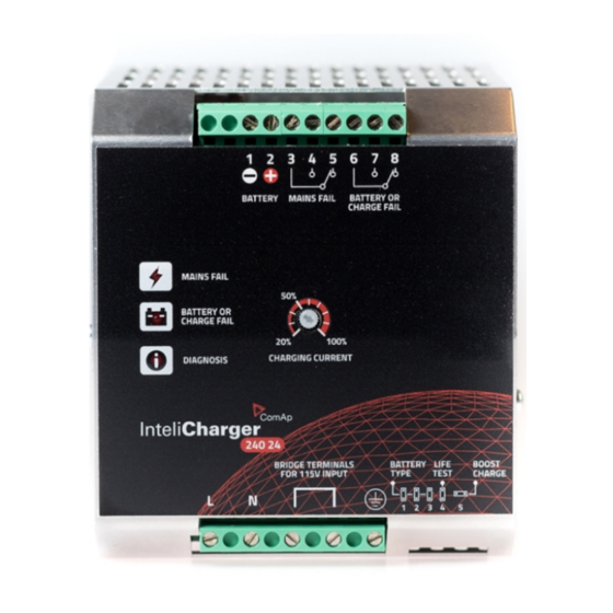
Signal output terminals
Isolated, voltage free, output contacts of mains fail alarm relay (pin 3,4 and 5) are active under AC input fail
conditions. See details in table below.
Mains fail?
YES
NO
Note: For better system reliability set up at least 5 s input delay when signal is further processed, for example
by PLC.
Isolated, voltage free, output contacts of battery or charge fail alarm relay (pin 6,7 and 8) are active under low
battery, wrong battery connection, charging fail or battery to be replaced conditions. See details in table below.
Battery or charge fail?
YES
NO
Note: In Recovery the Battery or charge fail indicator
closed) to indicate a battery with very low voltage.
Relay contact rating
30 V
, 1 A
DC
Max
60 V
, 1 A
AC
Min
5 V
, 1 mA
DC
Status indicators
Mains fail indicator.
Battery or charge fail indicator.
Diagnostic indicator.
Charging phase
Float
Absorption
InteliCharger 240 24 Reference Guide
for details.
Relay output pair
pin 3–4
pin 3–5
open
closed
closed
open
Relay output pair
pin 6–7
open
closed
is OFF but the Relay is in failure mode (pin 6–8
Resistive load (EN 60947-4-1)
Min. permissive load.
Diagnostic indicator
1 blink / 2 s
1 blink / s
Fail indicator
– led on
– led off
Fail indicator
pin 6–8
closed
open
Fail indicator
– led off
– led off
– led on
– led off
10