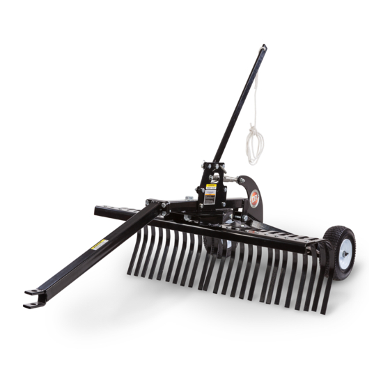
DR 48" LANDSCAPE RAKE 안전 및 작동 지침 매뉴얼 - 페이지 6
{카테고리_이름} DR 48" LANDSCAPE RAKE에 대한 안전 및 작동 지침 매뉴얼을 온라인으로 검색하거나 PDF를 다운로드하세요. DR 48" LANDSCAPE RAKE 16 페이지.

Specifications
Tine QTY
Wheels
Working Width
Hitch Type
2
1
6
8(24X)
7
13
11
14
12(24X)
15
Figure 2
Height Adjustment Plate
pointing forward
Bolts
Wheels
Axle
Frame
M20 Washer
Cotter Pin
Figure 3
Axle
M18 Bolt
Assembly
Frame
M18 Locknut
M12 Locknuts
Figure 4
®
DR
6
48" LANDSCAPE RAKE
24
Pneumatic, 12" Diameter
48"
Pin
Assembling the DR 48" Landscape Rake
Parts Supplied in Hardware Bag (Figure 2):
3
5
4
Item #
1 ............. 40945 .............. Bolt, Hex, M24 X 100 ................................. 1
2 ............. 40971 .............. Bolt, Hex, M18 X 90 .................................... 1
3 ............. 40955 .............. Bolt, Hex, M12 X 70 .................................... 5
10
9
4 ............. 40942 .............. Bolt, Hex, M12 X 40 .................................... 4
5 ............. 40961 .............. Bolt, Hex, M16 X 45 .................................... 1
6 ............. 40946 .............. Washer, Flat, M24 ....................................... 2
7 ............. 40972 .............. Nut, Nylon Lock, M18 ................................ 1
8 ............. 40948 .............. Bolt, Carriage, M10 X 30 ............................. 24
16
9 ............. 40943 .............. Nut, Nylon Lock, M12 ................................ 9
10 ........... 40962 .............. Nut, Nylon Lock, M16 ................................ 1
11 ........... 40947 .............. Nut, Nylon Lock, M24 ................................ 1
12 ........... 40952 .............. Nut, Nylon Lock, M10 ................................ 24
13 ........... 40976 .............. Washer, Flat, M20 ....................................... 2
14 ........... 40977 .............. Pin, Cotter, 4 X 50 ....................................... 2
15 ........... 40954 .............. Pin, Retaining .............................................. 2
16 ........... 40953 .............. Pin, Hitch..................................................... 2
Compare the contents of the Hardware Bag with the "Parts Supplied" list above.
If you have any questions please contact us at www.DRpower.com or call 1-800-
DR-OWNER (376-9637) for assistance.
Locknuts
Tools Needed:
1.
Pivot Disc
2.
on Bottom
M12 Bolts
3.
4.
Tow Bar
Part #
Description
17mm Wrench
18mm Wrench
Two 19mm Wrenches
Two 24mm Wrenches
Two 27mm Wrenches
Two 36mm Wrenches
Install the Wheels to the Axle Frame, with the Valve Stems facing out, using
the M20 Flat Washers and Cotter pins (Figure 3).
Install the Height Adjustment Plate onto the Axle Frame so that it is
pointing forward (away from the Wheels) using three M12 X 70 Hex Bolts
and Locknuts. Tighten the hardware using two 19mm Wrenches.
Position the Frame so that the Pivot Disc is on the Bottom (Figure 4).
Install the Tow Bar to the Frame so that it is angled down using four M12 X
40 Bolts and Locknuts. Tighten the hardware using two 19 mm Wrenches.
Install the Axle Assembly to the rear of the Frame using the M18 X 90 Bolt
and Locknut. Use two 27mm Wrenches to tighten the Hardware. Do not
over tighten; the Axle Assembly should be able to rotate freely.
Qty
