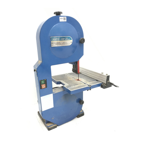
Draper BS190 사용 설명서 - 페이지 14
{카테고리_이름} Draper BS190에 대한 사용 설명서을 온라인으로 검색하거나 PDF를 다운로드하세요. Draper BS190 20 페이지. Two wheel bandsaw
Draper BS190에 대해서도 마찬가지입니다: 사용 설명서 지침 (20 페이지)

ASSEMBLY cont'd
TENSIONING THE BLADE
Turn the blade tensioning knob ✹✌ Fig.22.
clockwise until the blade is tensioned. The blade
tension can be checked by pushing sideways on the
blade midway between the two wheels. When the
tension is correct the blade should move slightly
from side to side with firm finger pressure.
NOTE: Do not overtighten the blade. Too much
tension may cause blade breakage. Too little tension
may cause the blade to slip on the wheels.
Removing the blade is the reverse of the
aformentioned procedure.
TRACKING THE BLADE
NOTE: The blade tension must be correctly adjusted
before tracking the blade.
1. Slowly turn the upper wheel ✺✌ Fig.23.
clockwise by hand and watch the blade on the
tyre. If the blade does not stay central on the tyre
the tracking will have to be adjusted.
2. To adjust the tracking, turn the tracking
adjustment knob ✻✌ on the rear of the saw
behind the upper wheel. Fig.24.
3a. If the blade moves towards the rear cover (away
from the front of the saw) turn the adjustment
knob anticlockwise while turning the wheel
slowly by hand until the blade centres correctly
on the tyre.
3b. If the blade moves away from the rear cover
(towards the front cover) turn the adjustment
knob clockwise while turning the wheel slowly
by hand until the blade centres correctly on the
tyre.
4. Now check the position of the blade on the other
wheel tyre, the whole width of the blade should
be on the tyre. If it is not re-adjust the tracking
until the blade is on both tyres.
5. Before switching 'ON' rotate the upper wheel by
hand in a clockwise direction for a few turns.
Check that the blade stays in position on the
tyres. Re-adjust the tracking if necessary.
6. Position the blade guard and secure using the
two blade guard mounting screws, see Fig.25.
7. Close the front cover and tighten the two locking
knobs.
8. Re-fit the table alignment screw, washer and
wing nut to the table.
ADJUSTING THE BANDSAW TABLE 90˚ TO THE
BLADE
1. Loosen the upper slide lock knob and raise the
blade guide assembly. Tighten the upper slide
lock knob.
2. Now loosen the table tilt lock knobs ✭✌ Fig. 15.
3. Place a small engineers/combination square on
the table beside the blade as shown in Fig.26.
4. Hold the edge of the table and carefully tilt the
table up or down until the top surface is at a 90˚
angle to the blade, tighten the table tilt lock
knobs.
Fig.23.
- 14 -
Fig.22.
✹✌
✺✌
Fig.24.
✻✌
Fig.25
Fig.26.
