Bosch 800 Series 설치 지침 매뉴얼 - 페이지 7

{카테고리_이름} Bosch 800 Series에 대한 설치 지침 매뉴얼을 온라인으로 검색하거나 PDF를 다운로드하세요. Bosch 800 Series 24 페이지. Built-in wall ovens
Bosch 800 Series에 대해서도 마찬가지입니다: 설치 매뉴얼 (40 페이지), 사용 및 관리 매뉴얼 (12 페이지), 설치 매뉴얼 (23 페이지), 설치 매뉴얼 (28 페이지), 설치 매뉴얼 (32 페이지), 사용 설명서 (32 페이지), 설치 매뉴얼 (32 페이지), 빠른 시작 및 안전 매뉴얼 (7 페이지), 사용 및 관리 매뉴얼 (40 페이지), 설치 매뉴얼 (40 페이지), 설치 매뉴얼 (32 페이지), 설치 지침 매뉴얼 (40 페이지), 설치 매뉴얼 (48 페이지), 사용 및 관리 매뉴얼 (33 페이지), 사용 및 관리 매뉴얼 (49 페이지), 빠른 시작 매뉴얼 (7 페이지), 빠른 시작 및 안전 매뉴얼 (13 페이지), 설치 매뉴얼 (32 페이지), 서비스 매뉴얼 (36 페이지), 설치 지침 매뉴얼 (29 페이지), 사용 및 관리 매뉴얼 (24 페이지), 사용 및 관리 매뉴얼 (40 페이지), 설치 지침 매뉴얼 (28 페이지)
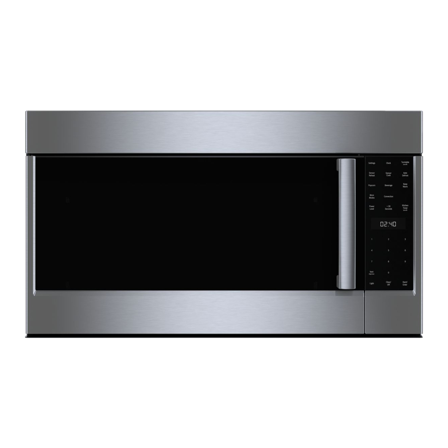
Bosch 800 Series 설치 지침 매뉴얼

Electrical Requirements

The unit requires a 120 volt, 60 Hz, 15 AMP (minimum) circuit. It is recom-
mended that the unit be installed on a separate circuit that serves only this
appliance.
This appliance is fitted with a 3-prong grounded electrical plug. Do not modify
the plug or use an adapter. If the plug does not fit with the available recep-
tacle, have a licensed electrician install a properly grounded outlet before
proceeding with the installation. The power cord length is approximately 46".
Installer - show the owner the location of the circuit breaker or fuse. Mark it for
easy reference.
Note: If you have any questions about the grounding or electrical instructions,
consult a qualified electrician or service person.
* Can also be installed using an electrical outlet in an adjacent cabinet within the area where the provided electrical cord can reach.
Always check electrical codes for requirements.

Drawer Installation

1. Place the drawer adjacent to the wall or cabinet
opening. Plug the power supply cord into the
electrical outlet.
2. Carefully guide the drawer into the prepared open-
ing. Avoid pinching the cord between the oven and
the wall.
3. Slide the drawer all the way until the mounting
flange makes contact with the face of the cabinet
for standard installation or side cleats for flush
installation. See Figure 7A.
4. Open the drawer. Using the 4 holes on the drawer
as a template, pre drill the cabinet using a
See Figure 7A.
5. Secure the drawer with the 4 screws supplied. See
Figure 7B.
6. Test operation to confirm that the Drawer Micro-
wave is functioning properly and the drawer opens
and closes freely.
English 7
1
/
" bit.
16
Suggested electrical
outlet location*
4"
Figure 6
Figure 7A
Parts supplied
4 Screws
Figure 7B
5"
Cleat
Mounting
flange