COMMUNICATIONS-APPLIED TECHNOLOGY AMCVIS 운영 매뉴얼 - 페이지 5
{카테고리_이름} COMMUNICATIONS-APPLIED TECHNOLOGY AMCVIS에 대한 운영 매뉴얼을 온라인으로 검색하거나 PDF를 다운로드하세요. COMMUNICATIONS-APPLIED TECHNOLOGY AMCVIS 16 페이지. Advanced multi-channel vehicle intercom system (amcvis) with digital crew control

1. SYSTEM COMPONENTS
1.1.
INTERCOM MASTER UNIT (IMU):
The IMU is the AMCVIS system controller. It contains the various audio circuits, power supply, two
radio interfaces and five intercom station interfaces. The components are housed in a splash-proof,
rugged metal housing that can be mounted in a wheeled vehicle or boat.
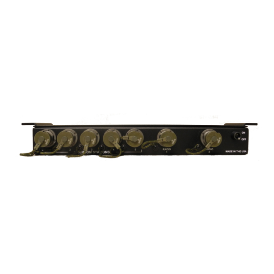
FIGURE 2: INTERCOM MASTER UNIT (IMU) FRONT PANEL
Controls, indicators and jacks include:
1. A power "ON/OFF" switch located on the front panel.
2. A red LED on the right side panel is the power ON indicator
3. A power jack located on the rear side panel.
4. Five jacks on the IMU front panel allow connection to the intercom control units (ICU).
5. Two radio interface jacks also on the front panel allow connection to the military and commercial
two-way radios.
6. A cover labeled "RADIO AUDIO LEVEL ADJUSTMENT" (held in place by two thumb screws to
provide environmental protection) allows access to the Radio #1 and Radio #2 RECEIVE and
TRANSMIT level adjustments, (one per radio).
7. Two Green LEDs on the side panel are the P-T-T indicators for Radio #1 and Radio #2.
8. There are also five side tone adjustments, (one per station), that are located inside the IMU. These are
not accessible from the outside of the unit (no field adjustments should be required).
FIGURE 3: REAR and SIDE of INTERCOM MASTER UNIT (IMU)
- 4 -
