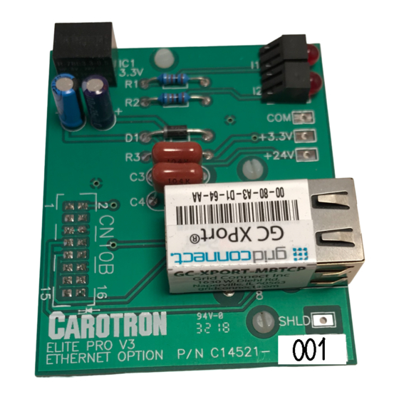
Carotron C14521-001 사용 설명서 - 페이지 2
{카테고리_이름} Carotron C14521-001에 대한 사용 설명서을 온라인으로 검색하거나 PDF를 다운로드하세요. Carotron C14521-001 18 페이지. Ethernet/ip

Table of Contents
1. General Description....................................................................................................... 3
2. Specifications ................................................................................................................ 4
2.1 Electrical ........................................................................................................... 4
2.2 Physical ............................................................................................................ 4
3. Installation ..................................................................................................................... 5
3.1 Physical Installation .......................................................................................... 5
3.2 Wiring Guidelines ............................................................................................. 5
4. I/O Details...................................................................................................................... 6
4.1 Module LEDs .................................................................................................... 6
5. Configuration Procedure.............................................................................................. 10
6. Standard Terms & Conditions of Sale ......................................................................... 17
Table 1: Connection LED .................................................................................................. 6
Table 2: Activity LED ......................................................................................................... 6
Table 3: Input (T→O) Assembly ........................................................................................ 7
Table 4: Modbus Status .................................................................................................... 7
Table 5: Fault Codes ......................................................................................................... 8
Table 6: Output (O→T) Assembly ..................................................................................... 9
Table 7: Drive Control........................................................................................................ 9
Figure 1: Dimensions......................................................................................................... 4
Figure 3: Logix 5000: Create New Module ...................................................................... 12
Figure 4: Logix 5000: Select Module Type ...................................................................... 13
Figure 5: Logix 5000: Define Module Properties ............................................................. 14
Figure 6: Logix 5000: Input Tags..................................................................................... 15
Figure 7: Logix 5000: Output Tags .................................................................................. 15
2
®
Output Assembly.......................................................................... 9
®
Configuration Tool........................................................ 10
