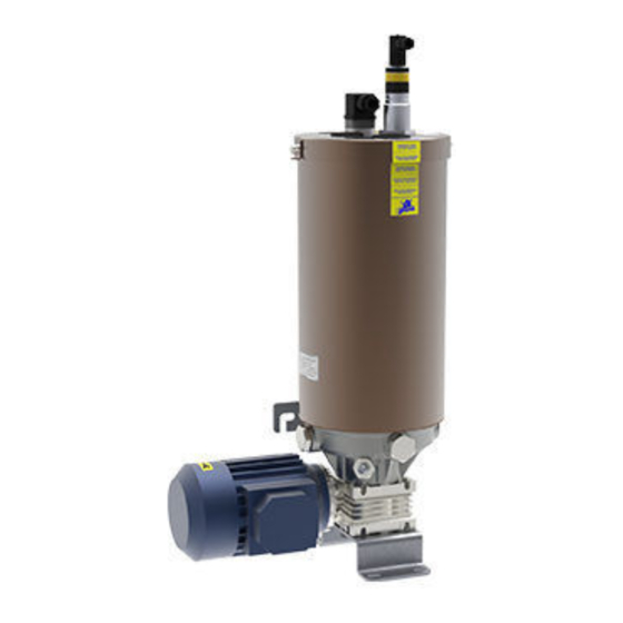
DROPSA 989004 사용자 및 유지보수 매뉴얼 - 페이지 6
{카테고리_이름} DROPSA 989004에 대한 사용자 및 유지보수 매뉴얼을 온라인으로 검색하거나 PDF를 다운로드하세요. DROPSA 989004 14 페이지.

8. TROUBLESHOOTING
The following diagnostic table indicates the main anomalies which may be encountered, the probable causes and
possible solutions. If you cannot solve the problem, do not attempt to disassemble the unit, but contact the
Engineering Department of DROPSA S.p.A.
N
A
NOMALY
Motor does not
01
operate
Pump does not
02
deliver lubricant
Pump operates but
does not deliver
03
lubricant to the
bearing- points
N
A
NOMALY
Lubricant reaches the
04
bearing-points in
incorrect quantities
Pump starts
05
lubricating but stops
immediately
Irregular flow rate
06
The system doesn't
07
reach the pressure
6
C
AUSE
Power supply failure
Ratiomotor does not operate
Reservoir is empty
Air-bubbles in lubricant
Obstructed suction pipe-line
Disconnected piping
Blocked progressive
distributor
C
AUSE
The distributor is not
correctly connected to the
bearing-points.
Delivery is not correct (only
for adjustable delivery pump
unit).
Faulty motor or high output
consumption.
Screw C, which secures the
pump element D and return
spring E, is loose (only for
adjustable delivery pump
unit).
Delivery valve dirty.
Delivery valve damaged.
Spring broken
Verify power supply system, and check the fuse
Replace the ratiomotor
Refill the tank with clean lubricant,
Disconnect main piping from pumping element fitting.
Operate the pump in the manual mode until lubricant
free of air-bubbles comes out of the fittings
Disassemble the pumping unit and clear the suction
pipe-line
Inspect piping and replace the wear pipes
Clear the distributor. Replace it, if necessary
Verify that the dosages are those indicated in the
system diagram
Adjust delivery by means of regulation screw
Allow the pump being cooled for a few minutes and try
again. If the problem still continues, contact the
Customer Service
Remove the pump element assembly from the pump
body and completely disassemble it.
To reassemble the pump element assembly see the
sequence in the diagram.
Check and clean all pump unit parts. Verify the
component integrity.
Warning: put some Loctite type sealant on screw C,
which is inserted into pump element D. Hold the pump
element between wooden vice clamps to prevent
damage to the lapped surface. Lock up very well the
element B.
Dismount the valve A, clean it and mount following the
showed sequence.
Replace the pumping unit.
R
EMEDY
R
EMEDY
