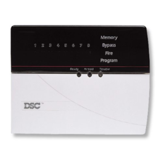
DSC PC5100 설치 지침 매뉴얼 - 페이지 6
{카테고리_이름} DSC PC5100에 대한 설치 지침 매뉴얼을 온라인으로 검색하거나 PDF를 다운로드하세요. DSC PC5100 12 페이지. 2-wire addressable device interface module

G
E
T
T
Not more than four
24AWG conductors
should be connected to a
single terminal as wire
bulk may cause improper
operation.
All devices must be enrolled as
individual zones on the system
by entering their serial numbers
(see section 3.2 "Enrolling
Devices").
If any of the system keypads indicate a PC5100 module tamper,
or if any zones show as open, or show a zone fault, there may
be a short on the AML loop. The PC5100 module and zones will
not be restored until the short is corrected - remove power
from the system and re-check the zone wiring.
2.4 Connecting the PC5100 Tamper
The PC5100 has a built-in tamper switch (SW1). If an external tamper
switch is being used, connect the switch according to the following
diagram.
If neither the built-in tamper nor an external switch is being
used, you must short the TAM and BLK terminals. If you do not
make this connection, a trouble condition will be indicated.
I
N
G
Total loop
current (mA)
4
S
T
A
R
Loop Current vs. Wiring Distance
22 AWG
distance (ft/m)
10
2880/878
20
1620/494
30
1010/308
40
771/235
50
600/183
60
500/152
70
400/122
80
321/98
90
250/76
100
200/61
110
165/50
120
135/41
130
115/35
140
106/32
150
100/30
160
98/29
170
96/28
T
E
D
18 AWG
distance (ft/m)
5143/1568
3645/1111
2520/768
1736/529
1250/381
980/298
800/244
720/220
500/152
310/95
220/67
155/47
130/39
126/38
124/37
122/36
120/35
