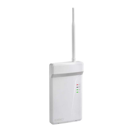
DSC 3g4000 설치 매뉴얼 - 페이지 5
{카테고리_이름} DSC 3g4000에 대한 설치 매뉴얼을 온라인으로 검색하거나 PDF를 다운로드하세요. DSC 3g4000 8 페이지. 3g (hspa) wireless alarm communicator

If the signal strength is too low (bottom signal LED off or flashing), the 3G4000 will move to Step 3 and
scan for carriers with sufficient signal strength and attach to the carrier. If the 3G4000 is connected to a
carrier with sufficient signal strength (minimum of bottom signal strength LED on solid), it will move to Step
4.
Step 2b – SIM card is not activated
The red LED will flash, the blue LED will be off and the signal strength LEDs will display the average signal
strength.
In this state, the 3G4000 is unable to register to the cellular network because it is inactive. The signal
strength indicated is from any nearby cell tower (including cellular towers belonging to non-roaming
partners) and does not necessarily reflect the signal strength of the intended network. The 3G4000 will
remain in this state until the SIM is activated. Once the SIM is activated, the 3G4000 will move to Step 2a.
Step 3 – Carrier Scanning due to insufficient signal strength
The 3G4000 will scan the surrounding cellular network and connect to the carrier to provide a signal
strength of at least 7 CSQ. When this action is being performed, all four LEDs will activate to show a
scanning sequence. The LEDs will cycle from top to bottom and then bottom to top. This cycle will continue
until the 3G4000 is connected to a carrier with a signal strength above 7 CSQ (minimum of bottom signal
strength LED on solid). This process can take several minutes.
Carrier Scanning, sequence repeats until complete.
Once this is completed, the 3G4000 will move to Step 4.
Step 4 - Acquire C24 Communications programming
The red LED will be on solid and the blue LED will flash. The flashing of the blue LED indicates that the
3G4000 has requested programming from C24 Communications and is waiting for a response.
Once remote programming is completed, the blue LED will switch to solid and the 3G4000 will move to
Step 5.
Step 5 – Receiver Initialization
The red LED and the blue LED are both solid and the signal strength LEDs are off.
When the 3G4000 sends a request to communicate with the central station, the top signal strength LED will
begin flashing.
When the central station communicates back with the 3G4000, the top signal strength LED will turn on solid.
When the 3G4000 sends a request to communicate with the next central station, the bottom signal
strength LED will begin flashing
and turn on solid when it receives a communication back from the central station.
If at least one of the central stations did not respond back to the communicator (or is not programmed), the
signal strength LED corresponding to that central station will turn off. Once the initialization sequence is
complete, the 3G4000 will move on to steady state operation.
STEP 6 - Mount the 3G4000
NOTE: If using a 3G4000 Trim plate, snap the 3G4000 back plate onto the trim plate before mounting
to wall. If flush mounting or using with an extension antenna, remove the provided break away from
the trim plate prior to mounting.
1. Using the mounting holes on the 3G4000RF backplate, mark the four screw locations. Drill the anchor
screw holes. NOTE: Check for cable conduits and water pipes before drilling.
2. Inspect the mounting surface. Ensure that the surface is flat and will hold the wall tamper closed when
mounted. Using anchor screws (not provided), mount the cabinet to the wall.
3. Run the cables through the cable entry [13] or through the cabinet cable run knockout [15].
4. Complete the connections on the terminal blocks [11].
5. Reattach the front cover [1] securely to the cabinet.
3
