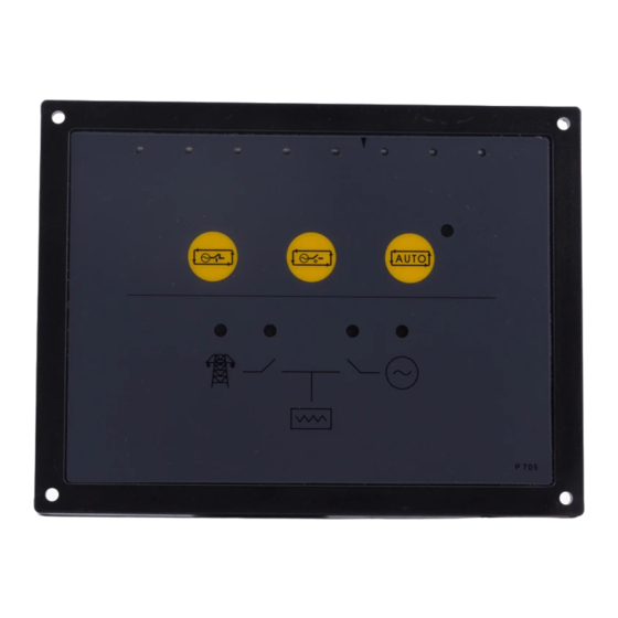
DSE DSE705 운영 매뉴얼 - 페이지 12
{카테고리_이름} DSE DSE705에 대한 운영 매뉴얼을 온라인으로 검색하거나 PDF를 다운로드하세요. DSE DSE705 13 페이지. Ats control module

8 DIMENSIONS
9 TYPICAL CONNECTIONS
Alternator Output
L3
L2
L1
N
21
1
2
To 'remote start' input of
engine controller (see note)
F2A
NOTES :
The remote start inputs of all DSE modules can be connected directly to the start/run output (terminal 3)
of the 705 ATS controller, providing that the DC supplies are common to each module.
+
Wiring of remote start relay above is shown for connection to an engine controller requiring a battery negative signal
Battery
to start the set (such as DSE controllers). Modules with different input requirements may need alternative wiring details.
If in doubt, consult the manufacturer of your engine control unit.
Terminals suitable for 22-16 awg (0.6mm
Tightening Torque = 0.8N-m (7lb-in)
- 12 -
057-043 705 Operating Instructions Issue 1.1 18/06/2007
705 ATS controller operators manual
Mechanical Interlock
Load
Electrical Interlock
G
F 2A
Normally open
* Close mains relay must be normally closed
to ensure fail safe operation
+
Close gen relay
14
20
SSO
Close Gen output
Start/Run output
SSO
3
Remote start relay
(see note)
+
2
-1.3mm
Dimensions:
165mm x 125mm x 29mm
(6.5" x 4.9" x 1.2")
Panel cut-out:
149mm x 109mm
(5.9" x 4.3")
Mounting Method:
4 x 4.2mm diameter holes suitable for M4
screws.
Mains / Utility supply
L3
L2
L1
M
FUSES 2A
*
NOTE
Normally closed
+
Close mains relay
13
16 17 18 19
SSO
Close mains output
Auxiliary Outputs
SSO
SSO
4
5
6
7
8 9
+
+
2
)field wiring
JR
N
SSO = Solid state outputs
= External 'Automotive' or 'Plug-in' type relays
15
12
11
10
