Danfoss VLT HVAC Drive FC 102 설치 지침 매뉴얼 - 페이지 8

{카테고리_이름} Danfoss VLT HVAC Drive FC 102에 대한 설치 지침 매뉴얼을 온라인으로 검색하거나 PDF를 다운로드하세요. Danfoss VLT HVAC Drive FC 102 10 페이지. Adjustable frequency drive - safe torque off
Danfoss VLT HVAC Drive FC 102에 대해서도 마찬가지입니다: 운영 매뉴얼 (16 페이지), 설치 매뉴얼 (20 페이지), 설치 지침 매뉴얼 (6 페이지), 설치 지침 매뉴얼 (12 페이지), 설치 매뉴얼 (18 페이지), 설치 지침 매뉴얼 (11 페이지), 설치 지침 매뉴얼 (8 페이지), 설치 매뉴얼 (6 페이지), 사용 설명서 (16 페이지), 설치 지침 매뉴얼 (6 페이지), 설치 매뉴얼 (16 페이지), 설치 매뉴얼 (8 페이지), 사용 설명서 (16 페이지), 설치 지침 매뉴얼 (6 페이지), 설치 매뉴얼 (6 페이지)
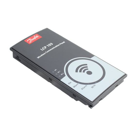
Danfoss VLT HVAC Drive FC 102 설치 지침 매뉴얼
Installation Instructions
1.4.5 Removing Current Sensors and Busbars
Remove the current sensor and busbars using the following procedure. Refer to Illustration 1.7.
1.
Remove the terminal label.
2.
Remove the 3 retaining nuts (M10), 1 from each output terminal busbar.
3.
Remove the 6 screws (M4) that connect the current sensors to the base plate, 2 from each sensor.
4.
Lift the 3 current sensors and busbars from the unit.
1
Current sensor
2
IGBT busbar retaining nut
3
Current sensor base plate screw (M4)
Illustration 1.7 Current Sensors and Busbars
8
500 A Current Sensor Kit for
E1/E2 Enclosure Sizes
®
VLT
FC 102, FC 103, FC 202, FC 302
4
5
6
Danfoss A/S © 10/2016 All rights reserved.
Output terminal busbar
Output terminal busbar retaining nut (M10)
Terminal label
MI92Q102