Dantel 49018 설치 및 운영 매뉴얼 - 페이지 5
{카테고리_이름} Dantel 49018에 대한 설치 및 운영 매뉴얼을 온라인으로 검색하거나 PDF를 다운로드하세요. Dantel 49018 14 페이지. Station selector
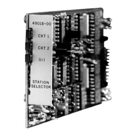
CIRCUIT DESCRIPTION
F
. 2 - 49018 S
IG
UBASSEMBLY
49018-0697 <90-00089>
-T
-H
M
P
C
O
OST
ODULE
IN
ONNECTIONS
8
RESET IN
POWER-UP
9
CLEAN IN
POWER-UP
P2-12
12
BUSY IN
P1-10
P1-12
A
B
C
D
STROBE
The strobe pulse also advances the digit counter which counts
up to three digits. Additionally, the strobe pulse initiates a clock
pulse output from the clock pulse delay circuit to gate the
station address latches. During the digit count, selected by the
digit strap option, the address in the address buffer latch is
compared to the preset address code selected by the miniature
10-digit switches. If the code matches, the matching station
address latch is not set and the corresponding station drivers
(1 or 2) output (P2-3 or P2-4) is enabled (grounded).
The last digit, whether the digit strapping is a one, two, or
three-digit code, will inhibit additional clock oulses from enter-
ing the digit counter. When a station driver is enabled, the
corresponding front panel LED will light.
The busy control output can be activated internally or exter-
nally. This circuit provides a ground output at P2-7 that can be
used to apply a busy tone to a subscriber phone or outside line.
The busy output can be activated internally when a *, #, or
A BCD input (depending on strapping) is decoded. The busy
output can also be activated by an external Power-up Busy
input at P2-12.
P2-3
P2-8
3
P2-4
P2-9
4
P2-5
5
P2-6
6
-10
P2-7
7
VDC
P2-10
10
P2-11
11
P1-1
P1-2
P1-3
P1-4
P1-5
49018
STATION
SELECTOR
SUBASSEMBLY
NOTE:
All connections to the 44020
Decoder outputs are made
directly through the J1/P1
and J2/P2 connectors
44020
HOST MODULE
CKT 1 OUT
CKT 2 OUT
DIGIT 0 OUT
DIGIT 1 OUT
BUSY OUT
CLEAN OUT
RING
GENERATOR
START
P
5
AGE