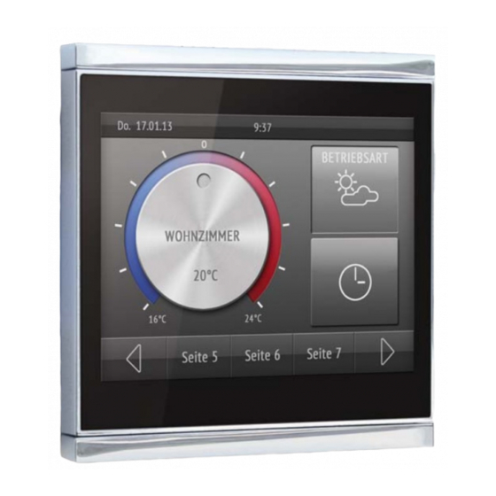
Elsner Corlo Touch KNX 기술 사양 및 설치 지침 - 페이지 8
{카테고리_이름} Elsner Corlo Touch KNX에 대한 기술 사양 및 설치 지침을 온라인으로 검색하거나 PDF를 다운로드하세요. Elsner Corlo Touch KNX 12 페이지. Display and touch switch
Elsner Corlo Touch KNX에 대해서도 마찬가지입니다: 기술 사양 및 설치 지침 (2 페이지)

2.2.3. Connection overview
1
2
3
6
Connect the bus voltage (no. 4, red/black terminals) and auxiliary voltage (no. 5,
yellow/white terminals). Use the attached breakout cable for connecting the digital/
analog inputs (no. 7). The cables for the inputs can be extendet to up to 10 m.
2.3. Instructions for assembly and operational
start-up
Never expose the sensor to water (e.g. rain) or dust. This can damage the electronics.
You must not exceed a relative air humidity of 95%. Avoid condensation.
After the operating voltage has been applied, the device will enter an initialization
phase lasting 5 seconds. During this phase no information can be received via the bus.
3.
Addressing the device
The programming mode for addressing at the bus is activated via the programming
button at the back of the housing or via the display.
Display Corlo Touch KNX • Status: 06.08.13 • Technical changes and errors reserved.
4
5
7
8
Breakout cable for analog/digital inputs:
Input 1: black/white
Input 2: black/yellow
Input 3: black/lilac
Input 4: black/blue
8
Fig. 7
1
Snaplock connector seating
2
Magnets (additional fixing)
3
USB socket
4
KNX terminal bus +/-
5
Terminal auxiliary supply 12...24V DC,
terminal configuration independent
from polarity
6
Micro SD socket (card contacts must
show in the direction of the display
when inserting it)
7
Analog/digital inputs socket
8
Programming button for addressing
the device at the bus (recessed)
Fig. 8
Addressing the device
