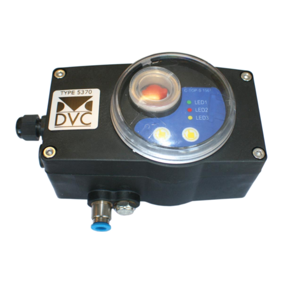
DVC 5370 설치, 운영 및 유지보수 매뉴얼 - 페이지 14
{카테고리_이름} DVC 5370에 대한 설치, 운영 및 유지보수 매뉴얼을 온라인으로 검색하거나 PDF를 다운로드하세요. DVC 5370 16 페이지. Mechanical limit switch with valve and led

4. 7. AS-I Bus connection
AS-I is a kind of field bus system. It could interconnect the controller, binary sensor (subordinate device)
with the control equipment of a upper computer (master control). The connection is conducted to
communicate by a flat cable which supply power to solenoid valve and sensor.
Type 5370 with AS-I must be equipped with flat cable, avoiding any interference.
The standard connection of Bus is to be connected with insulated tapping point with 2m cable.
The AS-I equipped with PCB could be connected with 4 solenoids and proximity switches at most.
4. 7. 1 . The connecting quantity of Type 5370 unit and the max. length of Bus Circuits
Each master controller could be connected with 62 AS-I control units at most (support model A and B).
In default situation, configuration as follows:
Programming: in default situation, the address is 1. And the address could be edited at will by master controller or
address editor.
Before using Type 5370, please note the following matters:
• Type 5370 should be installed on the valve/actuator correctly and tightly. Otherwise, water will be
infiltrated into equipment which will lead to the damage of device or be unable to be used normally.
• To inspect if all electric wires are OK in order to avoid influencing signal.
• To inspect piston and indicator could be moved by not touching with position detector. To make sure
the detector is set on the correct detecting height.
• To inspect if the compressed air in controller interface is eligible.
• To make sure the power is on. At least there's one LED light is lightened.
13 / 15
