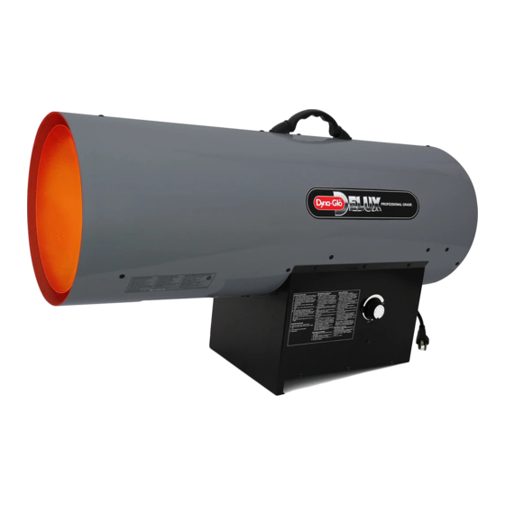
Dyna-Glo Delux RMC-FA300DGD 사용 설명서 및 부품 설명서 - 페이지 3
{카테고리_이름} Dyna-Glo Delux RMC-FA300DGD에 대한 사용 설명서 및 부품 설명서을 온라인으로 검색하거나 PDF를 다운로드하세요. Dyna-Glo Delux RMC-FA300DGD 11 페이지. Delux propane construction heater
Dyna-Glo Delux RMC-FA300DGD에 대해서도 마찬가지입니다: 사용 설명서 및 부품 설명서 (12 페이지)

Dyna-Glo
TM
Delux Operating Instructions and Parts Manual
Models RMC-FA300DGD
General Safety Information
(Continued)
Minimum heater clearances from
combustibles:
Outlet: 8 Ft.
Sides: 2 Ft.
Top: 6 Ft.
Rear: 2 Ft.
- Locate heater on stable and level
surface if heater is hot or running.
- Keep children and animals away from
heater.
- Turn off propane supply and unplug
heater when not in use.
- When used with optional thermostat,
heater may start anytime.
- Never block air inlet (rear) or air outlet
(front) of heater.
- Never move, handle, or service a hot,
operating, or plugged-in heater.
- Do not alter heater. Keep heater in its
original state.
- Do not use heater if altered.
- Never attach ductwork to front or rear
of heater.
Clean Heated
Air Out (Front)
Combustion Chamber
Air For Heating
Figure 2 – Cross Section Operational View
For Technical Support or Troubleshooting, Call: 1-877-447-4768, 8:30 am - 4:30 pm CST
- Use only original replacement parts.
This heater must use design-specific
parts. Do not substitute or use generic
parts. Improper replacement parts
could cause serious or fatal injuries.
- Do not adjust regulator below 7 PSIG
or above 10 PSIG.
Theory of Operation
FUEL SYSTEM
The hose/regulator assembly runs from
the propane supply to the heater itself.
After the gas runs through the hose
and regulator, it passes through the
solenoid valve and out the nozzle into
the combustion chamber.
AIR SYSTEM
The internal motor turns the fan, which
pushes air around and through the
combustion chamber. Here the air is
heated and provides a constant stream
of warmth.
IGNITION SYSTEM
The spark module sends voltage to the
ignitor. The ignitor ignites the fuel and
air mixture.
Ignitor
Fan
Nozzle Solenoid Valve
PCB Control
Spark Module (Spark Ignitor)
Air For Combustion
Motor
Cool Air In (Back)
On/Off Switch
Power Cord
Hose / Regulator
Assembly
3
SAFETY CONTROL SYSTEM
This system shuts the heater down if
the flame is extinguished. The fan and
motor will continue to operate, but
there will not be any heat.
PROPANE SUPPLY
All propane gas and tanks are to be
provided by the user.
This heater should only be used with
a tank that has a vapor withdrawal
system. Refer to the Standard of
Storage and Handling of Liquefied
Petroleum Gas, ANSI/NFPA 58, Chapter
5. Your local fire department or library
will have this information.
Two factors will dictate how much
propane is used from each tank:
1. The amount of gas in each tank.
2. The surrounding air temperature at
each tank.
The chart below shows how many tanks
should be used at a given tempera ture.
This heater should not be operated with
a tank smaller than 100 pounds.
Average
Temperature (°F)
at Tank Location
40
32
Use larger tank
20
Use larger tank
10
Use larger tank
0
Use larger tank
-10
Use larger tank
-20
Use larger tank
As the tempera ture drops, less gas is
vaporized, so a larger tank may be
necessary in very cold weather. Never
operate this heater with a tank smaller
than 100 pounds. Your local propane
dealer can help you select the proper
tank size and configuration.
www.ghpgroupinc.com
Number
of Tanks
3
