DYNACO 79-001 설치 지침 매뉴얼 - 페이지 4
{카테고리_이름} DYNACO 79-001에 대한 설치 지침 매뉴얼을 온라인으로 검색하거나 PDF를 다운로드하세요. DYNACO 79-001 6 페이지. Hifi hospital, original replacement pcb

( ) Using a soldering iron, connect wire from left speaker output terminal strip to eyelet #12 on
PCB.
( ) Using a soldering iron, connect wire from right speaker output terminal strip to eyelet #13 on
PCB.
( ) Using a soldering iron, connect wire from V3, pin #4 to eyelet #14 on PCB.
( ) Using a soldering iron, connect wire from V4, pin #6 to eyelet #22 on PCB.
(
) Using a soldering iron, connect wire from chassis mounted power supply filter capacitor
"square" symbol terminal to eyelet #19 on PCB.
(
) Using a soldering iron, connect wire from chassis mounted power supply filter capacitor
"triangle" symbol terminal to eyelet #20 on PCB.
( ) Using a soldering iron, connect wire from right bias potentiometer to eyelet #21 on PCB.
This completes the wiring portion of this kit. We recommend double checking your work and
wire connections prior to final assembly.
FINAL ASSEMBLY and ADJUSTMENT
(
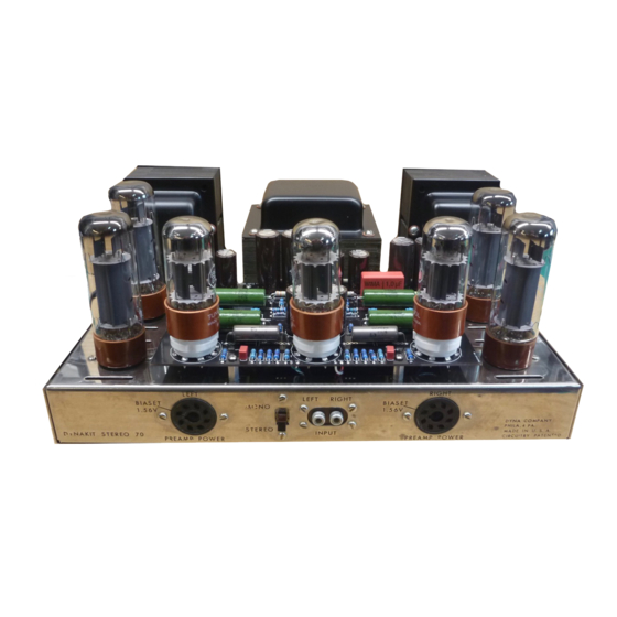
) Prior to attaching top and bottom covers, turn amplifier over ("right side up") and install all
seven (7) tubes.
( ) Using a flat blade screwdriver, adjust both bias pots fully counter clockwise (CCW).
WARNING: The following seven (7) steps are required to set correct bias voltage on left
and right channels. LETHAL VOLTAGES will be present !! If you are unfamiliar with
working in the presence of high voltage OR with high voltage, have a professional or
someone with experience in high voltage perform the following seven (7) steps. Note:
Bias adjustment is not absolutely necessary, although recommended for highest audio
quality, the amplifier can be safely operated with both bias potentiometers turned fully
counter clockwise (CCW).
(
) Clear area around and under amplifier of any and all metallic objects (solder, tools, scrap
wire, etc.).
(
) Using a DC volt meter (VOM), (available from Radio Shack, P/N 22-810 or equiv.) set
voltage range to measure up to 5 volts dc (VDC).
( ) Connect positive (red) meter lead to "BIASET" pin of left socket on front of amplifier.
( ) Connect negative (black) meter lead to chassis.
( ) Plug amplifier into AC outlet and turn on amplifier (allow two (2) minutes for warm up time).
( ) Adjust left bias potentiometer for approx. 1.56 VDC.
( ) Repeat last four (4) steps for the right channel.
( ) After successful bias adjustments, re-attach top and bottom covers with four (4) screws.
4
