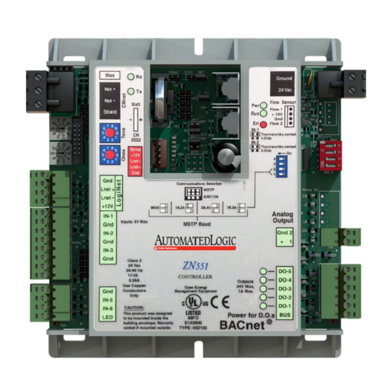
Automated Logic ZN551 기술 지침 - 페이지 6
{카테고리_이름} Automated Logic ZN551에 대한 기술 지침을 온라인으로 검색하거나 PDF를 다운로드하세요. Automated Logic ZN551 18 페이지. Control module

Wiring inputs and outputs
Wiring specifications
ZN551 Control Module • Rev. 3/17/2005
4
Set the communication type and baud rate.
Set Communications
For...
Selection jumper to...
ARC156
ARC156
MS/TP
MSTP
NOTE Use the same baud rate for all control modules on the network
segment.
5
Insert the power screw terminal connector into the ZN551's power
terminals.
6
Verify communication with the network by viewing a module status
report in WebCTRL.
Wire the ZN551's inputs and outputs as follows.
Input wiring
Input
Maximum length
0–5 Vdc
1000 feet
(305 meters)
Thermistor
1000 feet
Dry contact
(305 meters)
RS room sensors
500 feet
(152 meters)
LogiStat
100 feet
(30 meters)
1
See the RS Room Sensors Technical Instructions (http://info.automatedlogic.com).
2
See the LogiStat Sensors Technical Instructions (http://info.automatedlogic.com).
Output wiring
To size output wiring, consider the following:
•
Total loop distance from the power supply to the control module, and
then to the controlled device
NOTE Include the total distance of actual wire. For 2-conductor wires,
this is twice the cable length.
•
Acceptable voltage drop in the wire from the control module to the
controlled device
•
Resistance (Ohms) of the chosen wire gauge
•
Maximum current (Amps) the controlled device requires to operate
6
Set DIP switches 1 and 2 to...
N/A. Baud rate will be 156 kbps
regardless of the DIP switch settings.
The appropriate baud rate. See the MSTP
Baud diagram on the control module.
Minimum gauge
Shielding
26 AWG
Shielded
22 AWG
Shielded
22 AWG,
Shielded or
unshielded
4 conductor
1
Unshielded
2
22 AWG
© 2005 Automated Logic Corporation
