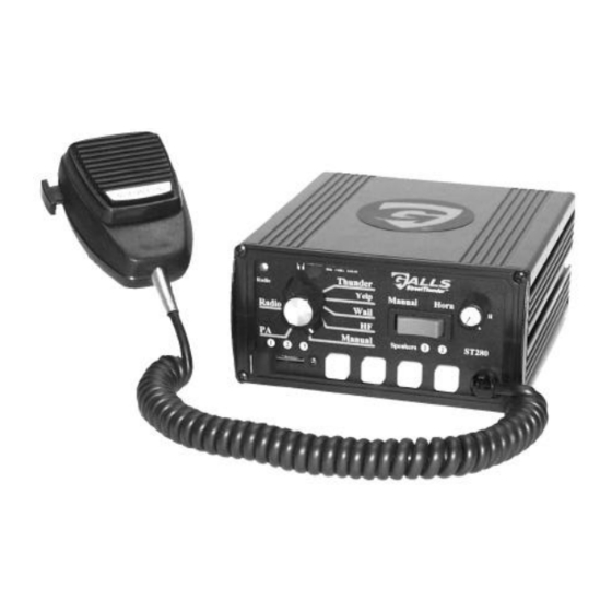
Galls Street Thunder ST280 설치 및 운영 지침 매뉴얼 - 페이지 8
{카테고리_이름} Galls Street Thunder ST280에 대한 설치 및 운영 지침 매뉴얼을 온라인으로 검색하거나 PDF를 다운로드하세요. Galls Street Thunder ST280 18 페이지. Siren amplifier & light controller
Galls Street Thunder ST280에 대해서도 마찬가지입니다: 설치 및 운영 지침 매뉴얼 (20 페이지)

Siren Wiring Connections
Optional Connections:
BLUE: (Pins 3 & 6) Input From Radio - Used for radio repeat. Connect
one blue lead to each terminal of the radio speaker or output
connector of the radio. Most radio outputs are isolated, in which
case polarity would not be important. Radios with polarity
sensitive outputs should be connected w/ the blue wire from pin 6
to the positive radio output, and the blue wire from pin 3 to the
negative radio output. Use #18 AWG wire.
GREEN: (Pin 10) AUX or Horn Ring - Used for remote Manual (or Air
Horn) control. Connect to the horn ring circuit or some other
remote switch. Circuit may be positive or negative with proper
jumper selection. See INSTALLER-SELECTABLE OPTION
section (page 3 and 4) for jumper details.
NOTE: Cut lead short if not used & insulate w/ electrical tape.
GRAY: (Pin 8) Park Kill (Cut-off) – This wire is used to de-activate the
siren when the vehicle is exited. Connect to dome light or added
door switch. Circuit may be positive or negative with proper
jumper selection. See INSTALLER-SELECTABLE OPTION
section (page 4) for jumper details.
NOTE: Be sure to cut lead short if not used and insulate with
electrical tape.
Testing -
Test all siren functions after installation to assure proper
operation. Test vehicle operation to assure no damage to vehicle.
:
(CONTD)
-7-
