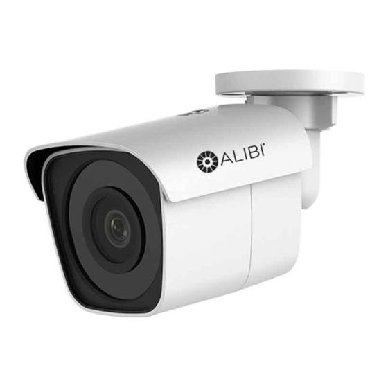
ALIBI ALI-NS4012R 빠른 설치 매뉴얼 - 페이지 5
{카테고리_이름} ALIBI ALI-NS4012R에 대한 빠른 설치 매뉴얼을 온라인으로 검색하거나 PDF를 다운로드하세요. ALIBI ALI-NS4012R 5 페이지. 2 mp ip 100 ft ir bullet camera
ALIBI ALI-NS4012R에 대해서도 마찬가지입니다: 빠른 설치 매뉴얼 (4 페이지)

Camera
ALI-NS4012R
One-key Reset, Anti-Flicker, Heartbeat, Mirror, Password Protection, Privacy Mask, Watermark,
General Functions
IP Address Filter
System Compatibility:
ONVIF (Profile S, Profile G), ISAPI
Simultaneous Live
Up to 6 channels
View
Up to 32 users
User/Host
3 levels: Administrator, Operator and User
Client
Alibi Central Management System (ACMS) 3.1 (or newer), ACMS-XP
Web Browser
Microsoft® Internet Explorer® (IE) Version 11 (or newer)
Interface
Communication
1 RJ45 10M/100M self-adaptive Ethernet port
Interface:
In-camera storage:
Built-in microSD / SDHC / SDXC slot, up to 128GB
Reset button
Yes
Smart feature set
Line crossing detection, intrusion detection, object removal detection, unattended baggage
Behavior Analysis
detection
Exception Detection
Scene change detection
Face Detection
Yes
General
-22 °F ~ 140 °F (-30 °C ~ 60 °C),
Operating Conditions:
Humidity 95% or less (non-condensing)
12 Vdc ± 25%, Φ 5.5 mm coaxial plug power
Power Supply
PoE (802.3af, class 3)
12 Vdc ± 25%, 0.5 A, max 5 W,
Power Consumption:
PoE (802.3af, 36 ~ 57V, class 3), 6.5 W
IR range
Up to 100 ft
Weather Proof:
IP67
Material
Metal
Camera: 6.18" × 2.83 × 2.48" (157 × 72 × 63 mm)
Dimensions:
Package: 8.5" × 4.8" × 4.7" (216 × 121 × 118 mm)
Camera: 1.05 lb (467 g)
Weight:
Package: 1.40 lb (636 g)
5
www.observint.com
Using the Waterproof Ethernet Fitting
Install the Waterproof Ethernet Fitting on the Ethernet cable end at the camera when moisture
or contamination exists in the area near the camera. The fitting includes several parts that must be
installed in a specific order. To install the fitting:
1.
Place the rubber O-ring over the camera drop cable end cap.
Push the O-ring up to the connector cap.
2.
If the network cable from the switch or router has a connector
on the end, cut off the connector.
3.
Place the Lock Nut onto the network cable from the router
or switch as shown in the drawing to the right. The inside
threads must be toward the camera end.
4.
Place the rubber basket onto the network cable above the lock
nut as shown.
5.
Place the end cap onto the network cable above the rubber
gasket as shown. The fingered end must be toward the router
or switch.
6.
Install an RJ-45 connector onto the network cable.
7.
Plug the RJ-45 connector with the network cable into the
camera network drop cable.
8.
Fit the end cap on the network cable onto the camera drop
cable end cap. Rotate the network cable end cap to lock it in
place.
9.
Push the rubber gasket fully into the end of the network cable
end cap.
10.
Screw the lock nut onto the network cable end cap until it is
fully seated.
Network drop
cable from
camera
Ethernet Fitting installed
Waterproof Ethernet Fitting assembled and connected
Network drop
cable from
camera
Drop cable
end cap
Rubber
O-ring
seal
RJ-45
connector
End cap
Rubber
gasket
Lock nut
Network
Network cable from
cable
from
router or switch
router or
switch
© 2019 Observint Technologies. All rights reserved.
