CORNING EDGE8-04U 설치 및 테스트 - 페이지 5
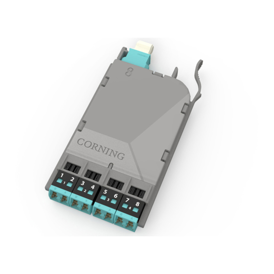
{카테고리_이름} CORNING EDGE8-04U에 대한 설치 및 테스트을 온라인으로 검색하거나 PDF를 다운로드하세요. CORNING EDGE8-04U 8 페이지. Tap module
CORNING EDGE8-04U에 대해서도 마찬가지입니다: 설치 및 테스트 (13 페이지)
6.
The Functionality of the Tap Module Splitters
Directionality
6.1
In simplest terms, the splitters inside a Tap module act like a divider of a one-way traffic flow –
in this case, light.
The even-numbered LC connectors in a
Tap module serve only for source input and
their traffic is split between the LIVE and
TAP outputs (Figure 7, top).
In the same fashion, the Tap module's
odd-numbered LC connectors receive live
traffic from the LIVE MTP input port. The
input traffic from the LIVE input port is split
between the LIVE LC odd fibers and the
MTP TAP port (Figure 7, bottom).
Tables 2 and 3 in Section 9 provide a full
representation of the source and output
positions
6.2
Tap modules therefore must be tested with directionality in mind. The source must be always
connected to the input of the splitter and the meter must be connected to the output of the splitter.
Connecting a source to the output of a splitter will result in high attenuation.
Wavelength Considerations
6.3
The splitters on multimode modules are optimized for 850 nm VCSEL (Vertical-cavity Surface-
emitting Lasers), thus when testing multimode systems, use only the 850 nm wavelength.
6.4
Single mode systems may be tested at both 1310 and 1550 nm.
7.
Installing an EDGE8™ LC-MTP Tap Module
NOTE: EDGE8 Tap modules are installed just like their normal EDGE8 module counterparts. Refer
to the Installation chapter in SRP 003-1002, EDGE8 Solution, for complete instructions. This
procedure covers module installation, trouble shooting, and other module-related topics as well.
Install the Tap module and its Tap MTP harness into your system housing.
8.
Referencing the Test Equipment for an LC-MTP Tap Module
8.1
Start by powering on the source and meter and allowing a minimum of 5 minutes for them to
warm up and stabilize.
For multimode systems: set the unit to the 850 nm wavelength.
For single mode systems: Set the unit to auto-switch between 1310 and 1550 nm
wavelengths.
STANDARD RECOMMENDED PROCEDURE 003-137-AEN | ISSUE 1 | JANUARy 2017 | PAGE 5 OF 8
Input into
LC # 2
Tap output
on MTP ber 1
Live
output
from
LC # 1
Tap output
on MTP ber 2
HPA-0755-EDGE8
LIVE
output
TAP
output
LIVE
source
TAP
output
Figure 7