CORNING Pretium EDGE ETM-7B-G 설치 및 테스트
{카테고리_이름} CORNING Pretium EDGE ETM-7B-G에 대한 설치 및 테스트을 온라인으로 검색하거나 PDF를 다운로드하세요. CORNING Pretium EDGE ETM-7B-G 9 페이지. Tap module
related literature |
SRP-003-794, Pretium EDGE
SRP-006-136, Multifiber Connector and Port Cleaning with the TKT-CLEAN-MFC-M kit
table of contents |
1. General .................................................................................................................................................1
2. Precautions ...........................................................................................................................................2
3. Tools and Materials ...............................................................................................................................2
4. Connector and Adapter Cleaning ..........................................................................................................2
5. Calculating System Loss .Budgets .......................................................................................................3
6. The Functionality of the Tap Module Splitters .......................................................................................5
7. Installing Pretium EDGE Tap Modules ...................................................................................................6
8. Referencing the Test Equipment for a Tap Module ...............................................................................6
9. Testing Pretium EDGETap Modules .....................................................................................................8
1.
General
1.1
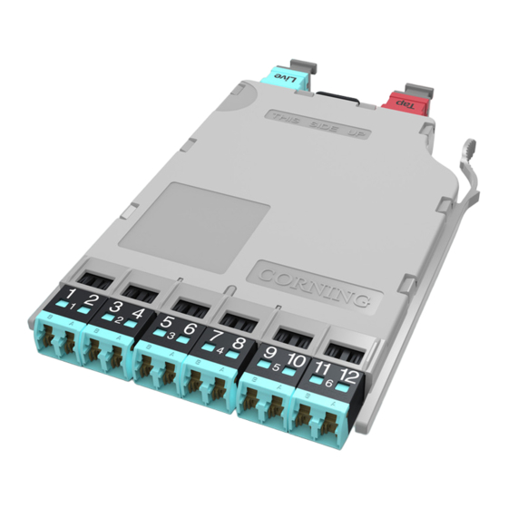
This procedure describes Pretium EDGE
Tap Modules, which are available for both multimode
and single mode applications. Compatible with all
Pretium EDGE rack-mountable connector housings,
TAP modules have twelve front-mounted shuttered
LC adapters and two MTP
(Figure 1).
1.2
The module contains 12 fiber optic splitters which divide the incoming optical signals into two
outputs, one for live link traffic and one for monitoring. The monitor traffic is routed via the "TAP"-labeled
MTP connector to a monitoring device which filters the data and sends it to various software tools for
analysis, where it is then viewed in application-layer software for security threats, performance issues, or
system optimization.
IMPORTANT: Please note that Tap module systems have two outputs for each input, which may
require two power meters, and depending on the system configuration, possibly require an additional
craftsperson in another location.
1.4
If this procedure is reissued, a summary of the changes will appear in this paragraph.
STANDARD RECOMMENDED PROCEDURE 003-126 | ISSUE 1 | OCTOBER 2012| PAGE 1 OF 9
Solution
®
connectors in back
®
Pretium EDGE
Installation and Testing
SRP 003-126, Issue 1
HPA-0753
Tap Module
®
Figure 1