CORNING Pretium EDGE ETM-7B-G 설치 및 테스트 - 페이지 6
{카테고리_이름} CORNING Pretium EDGE ETM-7B-G에 대한 설치 및 테스트을 온라인으로 검색하거나 PDF를 다운로드하세요. CORNING Pretium EDGE ETM-7B-G 9 페이지. Tap module
7. Installing a Pretium EDGE Tap Module
7.1
Pretium EDGE Tap modules are installed just like their normal Pretium EDGE module counterparts.
Refer to the Installation chapter in SRP-003-794, Pretium EDGE Solution, for complete instructions. This
procedure covers module installation, trouble shooting, and other module-related topics as well.
7.2
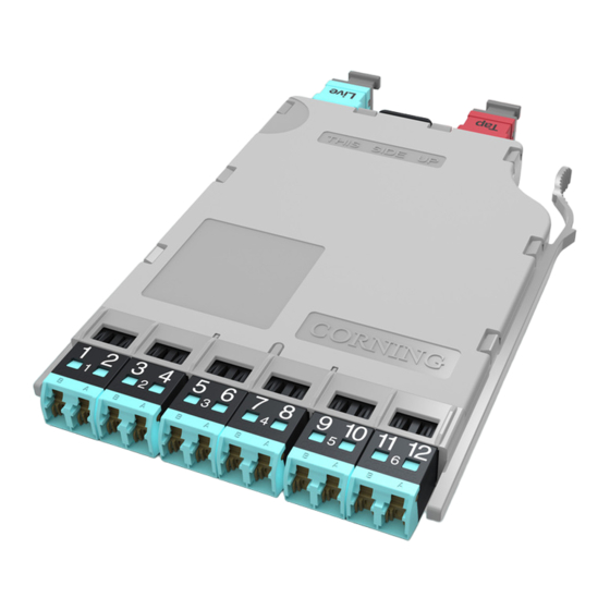
Install the Tap module and its Tap MTP harness into your system housing (this procedure illustrates an
MTP to LC harness).
8.
Referencing the Test Equipment for a Tap Module
8.1
Start by powering on the source and meter and allowing a minimum of 5 minutes for them to warm up
and stabilize.
For multimode systems: set the unit to the 850 nm wavelength.
For single mode systems: Set the unit to auto-switch between 1310 and 1550 nm wavelengths.
8.2
To reference the source and two meters:
Step 1:
Clean and insert the SC-end of the SC
to LC jumper (Reference Jumper no. 1,
or RJ1) into the output of the light
source.
Step 2:
Clean and insert the LC end of RJ1
jumper into the LC port adapter of
Meter no. 1 (M1) (Figure 8).
For multimode only: Wrap the jumper 5 times and
secure it in a 25 mm mandrel with tape (standard
50 µm multimode procedure).
Step 3:
Verify that RJ1 is acceptable at your
system's wavelength(s) and reference
this power to 0.00 dB.
Step 4:
Disconnect and move the meter-end LC
of RJ1 to Meter no. 2 (M2) and repeat
step 3. Disconnect M2 after this step.
Step 5:
Clean and insert the LC end of RJ1 into an LC adapter.
STANDARD RECOMMENDED PROCEDURE 003-126 | ISSUE 1 | OCTOBER 2012 | PAGE 6 OF 9
22 mm mandrel wrap for multimode only
Do NOT
disconnect
Light Source
(Tx)
HPA-0758
Reference
Jumper no.1
RJ1
0.00
Meter no. 2
Meter no. 1
(RX)
(RX)
M2
M1
Figure 8