CORNING Pretium EDGE ETM-7B-Q 설치 및 테스트 - 페이지 5
{카테고리_이름} CORNING Pretium EDGE ETM-7B-Q에 대한 설치 및 테스트을 온라인으로 검색하거나 PDF를 다운로드하세요. CORNING Pretium EDGE ETM-7B-Q 9 페이지. Tap module
6.
The Functionality of the Tap Module Splitters
Directionality
6.1
In simplest terms, the splitters inside a Tap module act like a divider of a one-way traffic flow – in this
case, light.
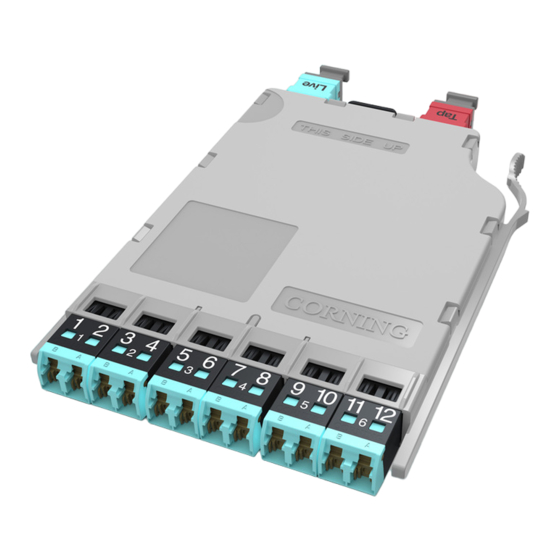
The even-numbered LC connectors in a Tap
module serve only for source input and their traffic is
split between the LIVE and TAP outputs (Figure 7,
top).
In the same fashion, the Tap module's odd-
numbered LC connectors receive live traffic from
the LIVE MTP input port. The input traffic from the
LIVE input port is split between the LIVE LC odd
fibers and the MTP TAP port (Figure 7, bottom).
Tables 2 and 3 in Section 9 provide a full
representation of the source and output positions
6.2
Tap modules therefore must be tested with directionality in mind. The source must be always connected
to the input of the splitter and the meter must be connected to the output of the splitter. Connecting a source to
the output of a splitter will result in high attenuation.
Wavelength Considerations
6.3
The splitters on multimode modules are optimized for 850 nm VCSEL (Vertical-cavity Surface-emitting
Lasers), thus when testing multimode systems, use only the 850 nm wavelength.
6.4
Single mode systems may be tested at both 1310 and 1550 nm.
STANDARD RECOMMENDED PROCEDURE 003-126 | ISSUE 1 | OCTOBER 2012 | PAGE 5 OF 9
Input
into
LC # 2
Tap Output
on MTP Fiber 1
Live
output
from
LC # 1
Tap Output
on MTP Fiber 2
HPA-0755
LIVE
output
TAP
Output
LIVE source
TAP
Output
Figure 7