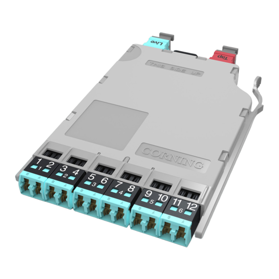
CORNING Pretium EDGE ETM-7B-Q 설치 및 테스트 - 페이지 7
{카테고리_이름} CORNING Pretium EDGE ETM-7B-Q에 대한 설치 및 테스트을 온라인으로 검색하거나 PDF를 다운로드하세요. CORNING Pretium EDGE ETM-7B-Q 9 페이지. Tap module

Step 6:
Clean and install an LC to LC jumper-
Reference Jumper no. 2 (RJ2) into M1
and the LC adapter (Figure 9).
Step 7:
Verify that the RJ1/ RJ2 mated pair are
acceptable with a loss ≤0.15 dB.
Step 8:
Disconnect RJ2's LC connector from the
LC adapter and protect it with a clean
dust cap until you are ready to start the
system testing.
Step 9:
Clean and install an LC to LC jumper-
Reference Jumper no.3 (RJ3) into M2
and the LC adapter (Figure 10).
Step 10: Verify that the RJ1/RJ3 mated pair are
acceptable with a loss ≤0.15 dB.
Step 11:
Disconnect RJ1's LC connector from
the LC adapter and protect it with a
clean dust cap.
Step 12: Leave the LC adapter on the end of RJ3 for the remainder of this procedure since it will be
required for mating to the TAP port test harness.
8.3
Referencing is now complete. Move the Light Source and RJ1 to the front of the Tap module; move
M2, RJ3, and the LC adapter to the end of the Tap harness; and move M1 and RJ2 to the Pretium EDGE
modules at the far end of the system (See Figure 11).
IMPORTANT: From this step on, do NOT disconnect the connectors on either the Light Source or meter port
adapters.
STANDARD RECOMMENDED PROCEDURE 003-126 | ISSUE 1 | OCTOBER 2012 | PAGE 7 OF 9
multimode only
RJ1
Do NOT
disconnect
Light
Source
HPA-0759
Dust cap
multimode only
RJ 1
Do NOT
disconnect
Light Source
HPA-0760
LC
adapter
Reference
Jumper no. 2
RJ2
Do NOT
disconnect
Figure 9
Do NOT
disconnect
LC
adapter
RJ3
0.15 dB
0.3 dB
M2
Figure 10
0.15 dB
M1
RJ2
M1
