Ceyear 4024E 유지 관리 매뉴얼 - 페이지 15
{카테고리_이름} Ceyear 4024E에 대한 유지 관리 매뉴얼을 온라인으로 검색하거나 PDF를 다운로드하세요. Ceyear 4024E 19 페이지. Spectrum analyzer
Attention: In case of the initial compensation, the following steps c) and d) shall be carried out. If steps c)
and d) have been carried out and "PowerMeter.powdoc" and "cal.txt" files have been generated under
the current directory, start from step 2 directly in case of re-compensation of other spectrometers. In
addition, when replacing another signal source or another cable for compensation, steps c) and d) shall
be carried out again.
c)
Click Measure Power Meter to measure the actual power value of the signal generator after passing
the cables. The interface is as shown in the following figure. When the test is completed, it will
prompt to generate the file "PowerMeter.powdoc".
d)
This step is mainly intended to measure the loss value of the cable. After the power meter is
calibrated and zeroed, connect 2.4 mm (m-m) low loss RF cable with the 1465H signal generator.
When the power sensor is connected with 2.4 mm (m-m) low loss RF cable, 2.4 mm (f-f) adapter
shall be used (when testing the 4024D/E, type 2.4 mm (f)-N (m) adapter shall be used). After that,
select the "Calibration Signal Source" of the compensation software. When the measurement is
completed, the status bar will prompt "Calibration Signal Source Finish", and "Cal.txt" will be
generated. The interface is as follows:
Fig. 11 Set Address Interface
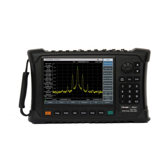
Fig. 12 Generate Power Meter File