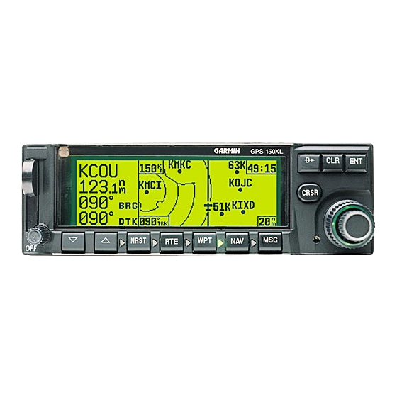
Garmin GNC 250 유지보수 및 수리 매뉴얼 - 페이지 19
{카테고리_이름} Garmin GNC 250에 대한 유지보수 및 수리 매뉴얼을 온라인으로 검색하거나 PDF를 다운로드하세요. Garmin GNC 250 20 페이지. Garmin gnc 250: quick reference
Garmin GNC 250에 대해서도 마찬가지입니다: 파일럿용 빠른 참조 매뉴얼 (25 페이지), 설치 매뉴얼 (44 페이지)

2.5
TROUBLESHOOTING CHART (COMM SECTION)
MESSAGE
Receiver has poor signal
reception (low
sensitivity)
Receiver audio is
distorted
Receiver audio volume is
low or intermittent
Receiver squelch is stuck
open (noise through audio
at all times)
Transmitter sidetone
audio is noisy or
distorted
Transmitter has low or no
power output
RECOMMENDED REPAIR
Check comm antenna in installation for intermittent
connection and/or high VSWR.
Verify connection between power/volume control
knob and CPU Board.
Verify connection between CPU Board and Comm
Receiver Board.
Replace comm chassis sub-assembly (see Section 3.2.2,
steps 1-7)
Replace CPU Board (see Section 3.2.4)
Verify connection between CPU Board and Comm
Receiver Board
Replace comm chassis sub-assembly (see Section 3.2.2,
steps 1-7)
Replace CPU Board (see Section 3.2.4)
Verify connection between power/volume control
know and CPU Board
Verify connection between CPU Board and Comm
receiver board
Replace comm chassis sub-assembly (see Section 3.2.2,
steps 1-7)
Replace CPU Board (see Section 3.2.4)
Verify connection between Control/Display unit and
CPU Board.
Verify connection between CPU Board and Comm
Receiver Board
Replace Control Display unit.
Replace comm chassis sub-assembly (see Section 3.2.2,
steps 1-7)
Replace CPU Board. (see Section 3.2.4)
Check comm antenna in installation for intermittent
connection and/or high VSWR
Verify connections from CPU Board to modulator
transistor Q34 and from Q34 to transmitter.
Verify connection between CPU Board and Comm
Receiver Board
Replace comm chassis sub-assembly (see Section 3.2.2,
steps 1-7)
Replace modulator transistor Q34 (see Section 3.2.2,
steps 8-14)
Replace CPU Board (see Section 3.2.4)
Check comm antenna in installation for intermittent
connection and/or high VSWR
Verify connection from CPU Board to modulator
transistor Q34 and from Q34 to transmitter.
Verify connection between CPU Board and Comm
Receiver Board.
Replace comm chassis sub-assembly (see Section 3.2.2,
steps 1-7)
Replace modulator transistor Q34 (see Section 3.2.2,
steps 8-14)
Replace CPU Board (see Section 3.2.4)
16
