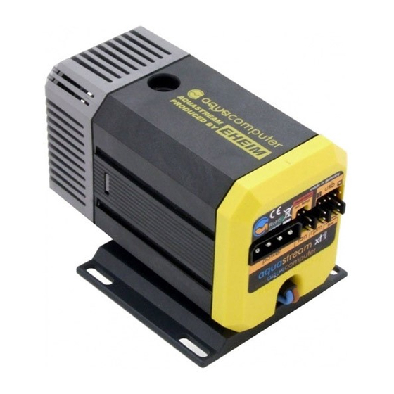
Aqua Computer AQUASTREAM XT USB 사용자 및 운영 매뉴얼 - 페이지 12
{카테고리_이름} Aqua Computer AQUASTREAM XT USB에 대한 사용자 및 운영 매뉴얼을 온라인으로 검색하거나 PDF를 다운로드하세요. Aqua Computer AQUASTREAM XT USB 16 페이지.
Aqua Computer AQUASTREAM XT USB에 대해서도 마찬가지입니다: 사용자 및 설치 설명서 (20 페이지)

aqua
computer
Version 11/2007
MANUAL AQUASTREAM XT
mode by jumper the option "activate by jumper mode (ext. Temperature)"
must be deactivated.
If you like to use a flow sensor, then you activate this flow sensor through the
button "flow rate sensor active". You can adjust settings for the flow sensor
and also see the current measured flow value in the lower area.
The other way you can activate the aquabus with the checkbox "aquabus
active". Moreover, the "aquabus address" can be changed, what becomes
necessary if you would like to attach two aquastream XT pumps by aquabus
to an aquaero.
In addition, if you want to control the aquastream XT through the aquaero,
you activate the option "prefer aquabus communication". Without this setting
the aquaero can only readout the pump. All other operating settings must be
carried out via the aquasuite software.
A restart of the pump must be carried out if you change the aquabus address
or reconfigure the connector. In this case, shut down your computer, wait for
a few seconds and switch it on again.
8.5. Window „Speed signal and alarm settings"
The aquastream XT evaluates various values over calculations as well as
sensors which can be put on an alarm. The rear status LED shines
permanently red at malfunctions or when an alarm value has been exceeded
or fallen below. If a speed signal cable is attached it is possible to "switch off
the speed signal in case of an alarm". The switching off only works when in
the configuration of the speed signal output the output of a static speed
signal was selected (with specification for revolutions per minute). In the other
three modes the signal of the fan, the flow sensor or the pump is always
forwarded independently of an alarm.
In the "alarm settings for speed signal output" you can define at which values
an alarm shall be given out. You can set upper respectively lower limits for
the external and internal temperature sensor as well as for the flow sensor.
The "current alarms" always displays all alarms which were established
independently of the alarm settings.
The number of measuring impulses indicates over which time period the
speed of the fan shall be determined. High values deliver very exact values
which are, however, updated only slowly. Small values accelerate the
measuring but measurement results are more inaccurate.
Page 12
Aqua Computer GmbH und Co. KG
© 2007
Gelliehäuser Str. 1 – D-37130 Gleichen - Germany
