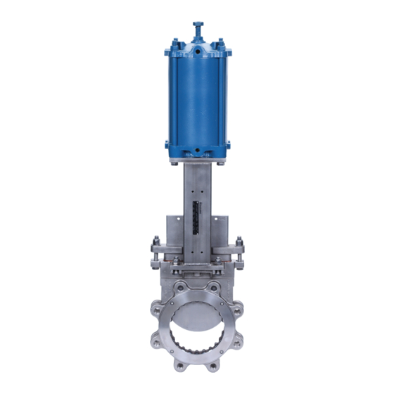
DeZurik KGC-MC 사용 설명서 - 페이지 11
{카테고리_이름} DeZurik KGC-MC에 대한 사용 설명서을 온라인으로 검색하거나 PDF를 다운로드하세요. DeZurik KGC-MC 17 페이지. Metal cutting knife gate valves

DeZURIK
KGC-MC METAL CUTTING KNIFE GATE VALVES
Reassembling Valve
1. Replace the packing gland (A4), screws (A5), washer (A6) and nuts (A7). Tighten the nuts evenly
and finger tight, plus 1/2 turn.
2. Reconnect the stem to the gate with the two screws and nuts.
3. Reconnect power to the actuator.
4. Pressurize the pipeline and inspect packing for leakage.
5. If packing leaks, tighten the adjustment nuts (A7) on top of the packing gland. Tighten the nuts
evenly and gently - just enough to stop the leak. Over tightening will cause excessive operating
forces, and will decrease the life of the packing.
Seat Replacement
See Figure 6 for component identification.
WARNING!
Pipeline pressure can cause personal injury or equipment damage. Relieve pipe-
line pressure before removing gate stem and packing gland nuts.
1. Relieve the pressure in the pipeline and close the valve.
WARNING!
Accidental operation of power actuator can cause personal injury or equipment
damage. Disconnect and lock out power to actuator before servicing.
2. Disconnect and lock out power to prevent accidental operation of the actuator.
3. Remove the pipeline flange bolts and pipe from the side of the valve body marked "SEAT". As an
alternative, remove both flanges, and remove the valve from the pipeline.
4. Remove four screws (A9) that hold seat ring in place.
5. Remove the seat ring (A10) from the body and rubber seat (A11) if supplied.
6. Remove the o-ring (A12).
7. Install the new removable seat:
a. Coat the o-ring (A12) with anti-seize compound or heavy grease and install the
o-ring (A12) into the body (A1).
b. If the valve is supplied with rubber seat, install rubber seat (A11) on the outside
diameter of the seat ring (A10).
c. Insert new seat ring (A10) into the body (A1) until the seat ring(A10) rests
against the shoulder in the body. The portion without serration must be in 3
& 9 o'clock positions. Orientation is shown on Figure 6.
d. Align the seat ring screw holes. Insert and tighten screws (A9) evenly.
November 2020
Page 11
D11060
