Allied Telesis AT-IMC100T/SCMM 설치 매뉴얼 - 페이지 10
{카테고리_이름} Allied Telesis AT-IMC100T/SCMM에 대한 설치 매뉴얼을 온라인으로 검색하거나 PDF를 다운로드하세요. Allied Telesis AT-IMC100T/SCMM 20 페이지. Fast ethernet industrial media converter

Hardware Description
2.4 Wiring the Fault Alarm Contact
The fault alarm contacts are in the middle of the terminal block as the picture shows below. Connect the wires to form a
normally close circuit. When fault events including power failure/port link failure occur, the loop will become an open circuit.
Insert the wires into the fault alarm contacts.
Note:
Use Copper Conductors Only, Tighten to 5 lb-in
Note:
The wire gauge for the terminal block should be in the range between 12~ 24 AWG.
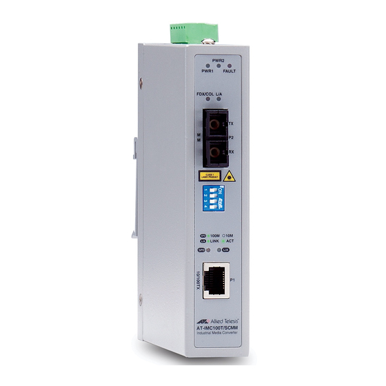
2.5 LED Indicators
LED indicators located on the front panel display the power status and network status of the Managed Industrial Switch.
Please refer to the following table for further details.
Table 2-1: Definition of LED indicators
LED
Color
P1
Green
P2
Green
Fault
Red
FDX/COL for Fiber
Amber
AT-IMC100T/SCSM and AT-IMC100T/SCMM Fast Ethernet Industrial Media Converters
Fault Alarm Contacts
FIGURE 2-5
Description
On
Power input 1 is active
Off
Power input 1 is inactive
Blink
---
On
Power input 1 is active
Off
Power input 1 is inactive
Blink
---
On
Power input 1 or 2 has failed
Off
Power input 1 or 2 are both functional or no power inputs
Blink
---
On
Full-duplex mode
Blink
Packet collistion occured
Off
Half-duplex mode
Wiring the Fault Alarm Contact
10
