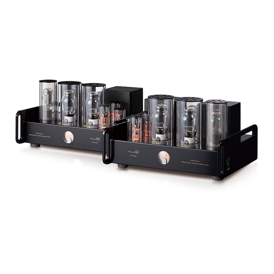
ALLNIC AUDIO A-2500 소유자 매뉴얼 - 페이지 7
{카테고리_이름} ALLNIC AUDIO A-2500에 대한 소유자 매뉴얼을 온라인으로 검색하거나 PDF를 다운로드하세요. ALLNIC AUDIO A-2500 14 페이지. 211/845 single-ended triode monoblock power amplifiers

other sources of such interference and from other equipment that could be susceptible to
such forms/sources of interference.
• When the A-2500s are moved from a cold to a warm environment, allow sufficient time for any
condensation to evaporate before plugging the A-2500s into an AC connection.
• Do not attempt any repairs.
B.
INPUTS
There are two (2) female inputs (See Figure 2). One accepts a balanced cable with a male XLR connector;
the other accepts a cable with a single-ended, RCA type male connector. On one chassis, these input
connections are located on the right (facing the back) rear of the chassis, with the balanced input closest
to the side edge. The inputs are on the left rear of the chassis on the other A-2500. Between the inputs,
there is a switch to select one of two pin configurations for a balanced cable (i.e., it changes the phase).
The top position is for pin 2" hot" and pin 3 "cold"; the bottom position is for the reverse (in both cases,
pin 1 is ground).
C.
SPEAKER TERMINALS
Each of the A-2500s is equipped with one pair of high-quality speaker terminals (See Figure 2). These
terminals are located in the middle of the rear panel of each A-2500 chassis, with the red marked terminal
for the live connection labelled positive "+" on the right, and with the return connection labeled negative
"-", to the left (facing the chassis rear). Between the plus and minus terminals is a switch that provides for
either 8 or 4 ohm impedance, as your speakers may require. The upper position of the switch is for 8 ohm
operation; the lower for 4 ohm operation. 8 and 16 ohm terminals are available by special order. The
terminals accept bare wire (not recommended), spade and banana type connectors.
D.
POWER CONNECTION
Connect the input interconnect and speaker cables before you insert the power cable into the
receptacle at the left (facing the back) rear of the chassis on one A-2500, and on the right on the
other (See Figure 2). The A-2500s use a standard 15 amp three prong male IEC connection for AC
input. You need to use power cords with a female 15 amp, three prong IEC connector at one end. The
Allnic ZL-3000 and ZL-5000 power cables will make an excellent match.
The A-2500s you have purchased are set internally for either AC 110/120 volt – 60 HZ, or 220/230 volt –
50 HZ operation. There is no way to change this to another AC setting without return of the A-2500s to
the factory for re-wiring, at the owner's cost, including transport both directions.
INITIAL POWER-ON
Once you have your A-2500s in place and all connections have been made to your source(s) and
preamplifier, you are ready to turn on the power for your A-2500s. Before you power up the A-2500s,
though, be sure you have:
7
