Bürkert 8792 조립 지침 매뉴얼 - 페이지 3
{카테고리_이름} Bürkert 8792에 대한 조립 지침 매뉴얼을 온라인으로 검색하거나 PDF를 다운로드하세요. Bürkert 8792 16 페이지. Position controller and process controller with ii 3g ex ec ic iic t4 gc / ii 3d ex tc iiic t135c dc approval
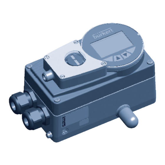
Bürkert 8792에 대해서도 마찬가지입니다: 조립 지침 매뉴얼 (16 페이지), 추가 지침 (12 페이지)
6.
Technical daTa.
Repeating accuracy
Temperature drift
Hysteresis
Operating voltage
Residual ripple
DC rated current
No-load current
l
0
Residual current
Rated insulation voltage
Short-circuit protection
Max. voltage drop at the switching
output compared to operating
voltage
Wire breakage safety /
reverse pole protection
Output function
Switching frequency
Protection class
english
8
7.
assembly
Caution!
Risk of injury from applied pressure!
Applied pressure may cause the spindle to move sud-
denly and injure fingers during installation.
•
Depressurize the device before installation.
The external position feedback is installed in two steps.
Step 1: Replace the standard display element with
the display element for the external position
feedback.
→
Loosen the 4 screws of the housing cover and open
the cover.
→
Remove the standard display element from the spindle
(see Fig. 1: ).
→
Push the display element with switching flags for the
external position feedback all the way onto the spindle
(see Fig. 1: ).
english
10
≤ 2 %
± 10 %
3 ... 15 %
10 ... 30 V DC
≤ 10 % U
ss
≤ 100 mA
≤ 15 mA
≤ 0.1 mA
≤ 0.5 kV
yes / clocking
≤ 1.8 V
yes / complete
Three-wire,
normally open
contact, PNP
≤ 0.02 kHz
IP65, IP67
6.1.
conformity with the following
standards
CE mark conforms to EMC Directive 2004/108/EC
Display element
with switching flags
for external
position feedback
Standard
display element
Fig. 1:
Replacing display element
Type 8791, 8792, 8793
english
9
Fastening
screws for
housing cover
english
11