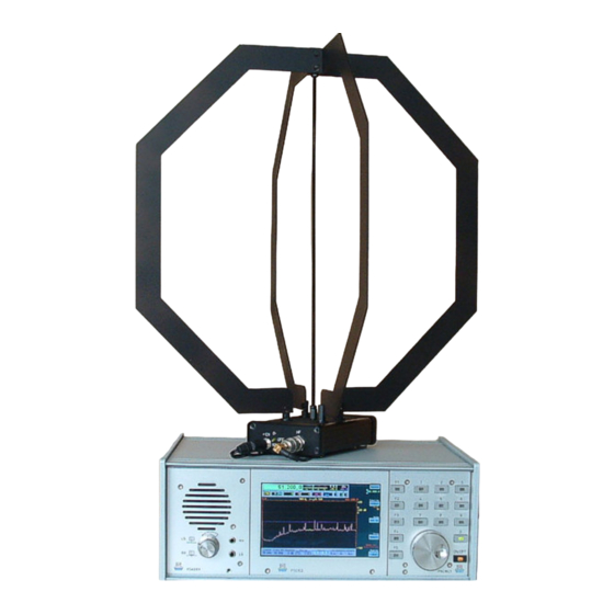
Burkhard Reuter RLA4 사양 및 작동 매뉴얼 - 페이지 6
{카테고리_이름} Burkhard Reuter RLA4에 대한 사양 및 작동 매뉴얼을 온라인으로 검색하거나 PDF를 다운로드하세요. Burkhard Reuter RLA4 9 페이지.

For complete control of all available modes, the remote supply voltage must be modulated with a logically
negative RS-232 signal (start bit = increased supply voltage, stop bits = supply voltage). The data format is
125 Baud 8N2 (8 data bits, no parity bit, 2 stop bits). Only one data word (8 bits = 1 byte) is transmitted.
The control of the antenna depends on the received byte as follows:
•
Value 0 to 126: Loop operation with setting the receiving direction from 0° to 180° in 127 steps.
•
Value 127: Whip operation.
•
Value 128 to 255: No reaction (reserved for future developments).
After switching on the remote power supply with a voltage of 6 V (up to a maximum of approx. 8 V), the
antenna is initially in whip mode. As soon as a data byte has been successfully received, the antenna
switches to the desired operating mode. The direction switching in loop mode is not possible linearly to the
control word. The main receiving directions of the two loops are largely preferred, as are the intermediate
stages (each 45° to the loops if both loops are equally active). In these directions, the antenna also
reaches its highest gain and works with the least distortion.
The effective rotation of the receiving direction between the 45° main directions is temperature and voltage
dependent. The corresponding control bytes result in a more or less large offset to this or more or less fast
panning between the main directions. In any case, it is possible to set clearly defined directions of
reception between the 45° main directions by varying the control bytes.
The purpose of such a fine-grained directional adjustment is not to detect a station to be received with a
maximum level. The "eight" characteristic of the loops with a very wide reception lobe allows optimal
reception with barely perceptible attenuation outside the exact main reception direction, even if the
antenna is not precisely aligned. Rather, the purpose lies in the most accurate possible positioning of the
zero point (minimum reception) with high suppression in this direction. The zero point has a sharp
directional characteristic and must therefore be set accurately. In most cases, there is a matching control
byte for the RLA4 for exact positioning of the zero point in the desired direction. However, this is different
for varying operating conditions (voltage, temperature).
The optional control unit for the RLA4 allows the generation of all possible bytes via a potentiometer. Thus,
by manually "tuning", the appropriate byte can be found by observing the reception on the receiver.
The control bytes 0 and 126 are equivalent. They switch the 1st loop (see switch on the antenna for loop
operation) either in phase, or directly opposite (180°) to the amplifier. Since the loop characteristic is
bidirectional, this corresponds exactly to the same reception conditions.
Tips for an ideal RLA4 operation
- The antenna is highly sensitive in spite of its small design and delivers high reception levels in
broadband. Sensitive receivers can be overmodulated. In such a case, you should place an attenuator or
better a preselector between the antenna and the RX.
- Even if you are tempted to position the antenna near the RX: Check its noise emissions and those of
other nearby devices, and place the antenna at a distance from it. Especially personal computers and their
peripherals (monitor, printer / scanner, SDR, network cables ...) as well as televisions and the like often
generate very high levels of interference.
- Prefer loop operation as often as possible. The whip operation usually only offers advantages at low
frequencies except when omnidirectional reception is desired.
Expansion of the direction control
In certain cases, the direction control's 127 steps allow only a relatively coarse setting (about 3° per step).
This is often too inaccurate to adjust the antenna to high suppression of a certain signal (positioning of the
receiving zero). Especially in the lower frequency range, the RLA4 reaches a suppression value of 50 dB
and more at exactly the zero point. The zero is very narrow. Even a turn of 1° reduces the attenuation.
Therefore, the direction control's resolution has been increased for the following antenna types:
- RLA4A from S/N 0095
- RLA4B from S/N 0097
- RLA4C
- Individual boards RLA4 from version F2
EDITION
DATE
1.5
8/19/19
K & M Burkhard Reuter
NAME
RLA4
B. Reuter
6
9
Page
of
