EPC EPC9514 빠른 시작 매뉴얼 - 페이지 2
{카테고리_이름} EPC EPC9514에 대한 빠른 시작 매뉴얼을 온라인으로 검색하거나 PDF를 다운로드하세요. EPC EPC9514 7 페이지. 6.78 mhz, 27w, 19 v regulated wireless power receiver using epc2016c
QUICK START GUIDE
DESCRIPTION
The EPC9514 demonstration board is a 6.78 MHz (Lowest ISM band)
highly resonant wireless power receiver capable of delivering up to
27 W as a 19 V regulated output when operating to the AirFuel™ standard
(excluding the BLE communications). This board is intended to power
products such as small laptops when used in a wireless power system.
The EPC9514 includes a Category 5 AirFuel Alliance compliant device coil
and circuit with high frequency Schottky diode based full bridge rectifier,
DC smoothing capacitor and 19 V regulator. The regulator is based on a
SEPIC converter that features a 100 V EPC2016C eGaN® FET. The power
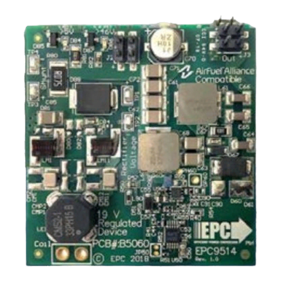
circuit is attached to the coil. A photo of the EPC9514 is shown in figure 1.
For more information on the EPC2016C eGaN FETs, please refer to the
datasheet available from EPC at www.epc-co.com. The datasheet should
be read in conjunction with this quick start guide.
DETAILED DESCRIPTION
The schematic diagram of the EPC9514 is shown in Figure 2 and comprises
a tuning circuit for the device coil with a common-mode choke for EMI
suppression, a high frequency rectifier and SEPIC based output regulator.
The EPC9514 is powered using a Category 5 AirFuel compliant device coil
and by default is tuned to 6.78 MHz for the specific coil provided with it.
The tuning circuit comprises both parallel and series tuning which is also
differential to allow balanced connection and voltage reduction for the
capacitors.
Two LEDs have been provided to indicate that the board is receiving
power with an un-regulated voltage greater than 4 V (green LED) and
the red LED will illuminate when the un-regulated voltage exceeds 44 V.
The EPC9514 has limited over-voltage protection using a TVS diode that
clamps the un-regulated voltage to 46 V. This can occur when the receive
coil is placed above a high power transmitter with insufficient distance
to the transmit coil and there is little or no load connected. During an
over-voltage event, the TVS diode will dissipate a large amount of power
and the red LED will illuminate indicating an over-voltage. The receiver
should removed from the transmitter as soon as possible to prevent the
TVS diode from over-heating.
Coil connection
Device
coil
2 |
C
Mx
L
M1
C
MPx
L
E1
C
Mx
L
M11
Tuning Network
Figure 2: Schematic diagram of the EPC9514 demo board.
| EPC – EFFICIENT POWER CONVERSION CORPORATION |
Table 1: Performance Summary (T
Symbol
Parameter
V
Un-regulated output voltage
Unreg
I
Un-regulated output current
Unreg
V
UVLO Enable
Unreg_UVLOR
V
UVLO Disable
Unreg_UVLOF
V
Output Voltage Range
OUT
I
Output Current Range
OUT
* Actual maximum current subject to operation temperature limits.
Un-Regulated
DC output
C
Rect
Q
1
Recti er
Demonstration Board EPC9514
= 25°C) EPC9514
A
Conditions
Un-regulated voltage rising
Un-regulated voltage falling
V
= 8.3 V
Unreg_min
V
= 8.3 V
Unreg_min
152 mm
Figure 1: EPC9514 demonstration system.
L
upper
C
D
Septic
rect
C
OUT
L
lower
Regulator
WWW.EPC-CO.COM
Min
Max Units
12.5
48
V
1.4*
A
25
V
12.5
V
18.75
19.25
V
0
1.4*
A
Regulated
DC output
19 V
DC
Load
| COPYRIGHT 2018