EPC EPC9514 빠른 시작 매뉴얼 - 페이지 3
{카테고리_이름} EPC EPC9514에 대한 빠른 시작 매뉴얼을 온라인으로 검색하거나 PDF를 다운로드하세요. EPC EPC9514 7 페이지. 6.78 mhz, 27w, 19 v regulated wireless power receiver using epc2016c
QUICK START GUIDE
DETAILED DESCRIPTION (continued)
The EPC9514 can be operated with or without the regulator. The regulator
can be disabled by inserting a jumper into position JP50 and connecting
the load directly to the unregulated output terminals. In regulated
mode, the design of the EPC9514 controller will ensure stable operation
in a wireless power system. The regulator operates at 300 kHz and the
controller features over current protection that limits the current drawn by
the regulator to 2 A.
The EPC9514 device boards come equipped with kelvin connections
for easy and accurate measurement of the un-regulated and regulated
output voltages. The rectified voltage current can also be measured using
the included shunt resistor. In addition, the EPC9514 has been provided
with a switch-node measurement connection for low inductance
connection to an oscilloscope probe that yield reliable waveforms.
The EPC9514 is designed to operate in conjunction with EPC9120 and
EPC9129 (33 W EPC9512) transmitter units.
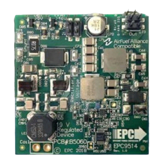
Figure 3 shows the proper connection method to the EPC9514.
QUICK START PROCEDURE
The EPC9514 demonstration system is easy to set up and evaluate the
performance of the eGaN FET in a wireless power transfer application.
Refer to Figure 3 for proper connection and measurement setup before
following the testing procedures.
The EPC9514 can be operated using any one of two alternative methods:
a. Using the regulator
b. Bypassing the regulator
EPC – EFFICIENT POWER CONVERSION CORPORATION |
Recti er voltage
Recti er voltage
> 4 V
LED
> 44 V
LED
Recti er DC Current
(75 m Shunt)
mV
Recti er Voltage
V
(12.5 V – 48 V
)
max
Coil tuning
Coil Connection
Figure 3: Proper connection and measurement setup for the receiver board.
WWW.EPC-CO.COM
a. Operation using the regulator
In this mode, the regulator is used to provide a fixed output voltage of 19 V
for the wireless power receiver and will limit the output current to 1.4 A.
1. Make sure the entire system is fully assembled (this includes the wireless
power transmitter) prior to making electrical connections and make
sure jumper JP50 is NOT installed. Connect the load to the regulated
output and connect all required instrumentation according to figure 3.
2. Power up the wireless power transmitter and observe that the EPC9514
receives power via the green LED, un-regulated voltage and output
voltage.
3. Once operation has been confirmed, observe the output voltage and
other parameters on the device board.
4. For shutdown, please follow steps in the reverse order.
b. Bypassing the regulator
In this mode, the regulator is disabled and the load connected directly to
the un-regulated output of the board. There is no protection against over-
current in this mode.
1. Make sure the entire system is fully assembled (this includes the wireless
power transmitter) prior to making electrical connections and make
sure jumper JP50 is installed. Connect the load to the un-regulated
output and connect all required instrumentation according to figure 3.
2. Power up the wireless power transmitter and observe that the EPC9514
receives power via the green LED, un-regulated voltage and output
voltage.
3. Once operation has been confirmed, observe the output voltage and
other parameters on the device board.
4. For shutdown, please follow steps in the reverse order.
Un-Regulated
Regulated load
load connection
connection
Disable Regulator
| COPYRIGHT 2018 |
Demonstration Board EPC9514
Regulated
voltage
V
measurement
Regulator
Switch-node
measurement points
| 3