Olympus BH2 Series 분해, 청소 및 재조립 - 페이지 3
{카테고리_이름} Olympus BH2 Series에 대한 분해, 청소 및 재조립을 온라인으로 검색하거나 PDF를 다운로드하세요. Olympus BH2 Series 45 페이지. Phase contrast
Olympus BH2 Series에 대해서도 마찬가지입니다: 문제 해결 및 조정 매뉴얼 (46 페이지), 완전한 분해, 청소 및 재조립 (23 페이지), 완전한 분해, 청소 및 재조립 (40 페이지), 매뉴얼 (6 페이지), 설치 매뉴얼 (9 페이지)
Clean Components of Light Inlet Assembly (BHT/BHTU) ____________________________________________ 33
Reassemble the Light Inlet Assembly (BHT/BHTU) _________________________________________________ 33
Reinstall Light Inlet Assembly (BHT/BHTU) ______________________________________________________ 35
Light Exit Assembly __________________________________________________________________________ 36
Servicing the Light Exit Assembly ______________________________________________________________ 37
Disassemble the Light Exit Assembly ___________________________________________________________ 37
Clean the Components of Light Exit Assembly ____________________________________________________ 39
Reinstall the Light Exit Assembly Frame onto the Base _____________________________________________ 41
Reassemble the Light Exit Assembly ____________________________________________________________ 41
Collimating the Integral Substage Lighting ________________________________________________________ 43
A Few Words About Dust Protection _____________________________________________________________ 43
Original Olympus Documentation _______________________________________________________________ 44
Olympus Research Microscopes Series BH2 (BHS) Repair Manual ____________________________________ 44
Olympus Research Corporation BH2 Repair ______________________________________________________ 44
How to Contact the Author ____________________________________________________________________ 44
Appendix 1 _________________________________________________________________________________ 45
Parts, Supplies, and Tools Referenced in this Document ___________________________________________ 45
Parts, Supplies, and Tools ____________________________________________________________________ 45
Sources for Parts, Supplies, and Tools __________________________________________________________ 45
Figure 1 - Head of a typical JIS screw ...............................................................................................................................8
Figure 2 - The viewing head locking screw (BHS/BHT) .....................................................................................................9
Figure 3 - The viewing head locking screw (BHSU/BHTU) ................................................................................................9
Figure 4 - Hold the threaded outer barrel stationary ......................................................................................................9
Figure 5 - Loosen and remove the slotted end-screw................................................................................................... 10
Figure 6 - Snug the knurled outer barrel down ............................................................................................................. 10
Figure 7 - Mounting disk from an old binocular head ................................................................................................... 10
Figure 8 - Place mounting disk into dovetail recess ...................................................................................................... 10
Figure 9 - Slide the mounting disk to expose the e-clip ................................................................................................ 10
Figure 10 - Secure mounting disk so the e-clip stays out .............................................................................................. 11
Figure 11 - Where there's a will there's a way .............................................................................................................. 11
Figure 12 - Carefully remove e-clip from the plunger shaft .......................................................................................... 11
Figure 13 - Remove mounting disk from dovetail recess .............................................................................................. 11
Figure 14 - Remove plunger rod from the inner barrel................................................................................................. 11
Figure 15 - Remove spring from stationary inner barrel ............................................................................................... 11
Figure 16 - Unscrew and remove knurled outer barrel................................................................................................. 12
Figure 17 - Clean the outside of stationary inner barrel ............................................................................................... 12
Figure 18 - Clean the bore of the stationary inner barrel ............................................................................................. 12
Figure 19 - Thoroughly clean the plunger rod ............................................................................................................... 12
Figure 20 - Clean threads and bore of the outer barrel ................................................................................................ 12
Figure 21 - Wash the grease from the extension spring ............................................................................................... 12
Figure 22 - Insert spring into the bore of the inner barrel ............................................................................................ 13
Figure 23 - Lightly grease the shaft of the plunger rod ................................................................................................. 13
Figure 24 - Insert plunger into bore of the inner barrel ................................................................................................ 13
Figure 25 - Apply grease to threads of the inner barrel ................................................................................................ 13
Figure 26 - Reinstall the knurled outer barrel ............................................................................................................... 13
Figure 27 - Test the motion of the spring-loaded plunger ............................................................................................ 13
Figure 28 - Place the mounting disk into dovetail recess .............................................................................................. 14
Figure 29 - Slide mounting disk to expose the shaft end .............................................................................................. 14
Figure 30 - Clamp mounting disk to keep shaft exposed .............................................................................................. 14
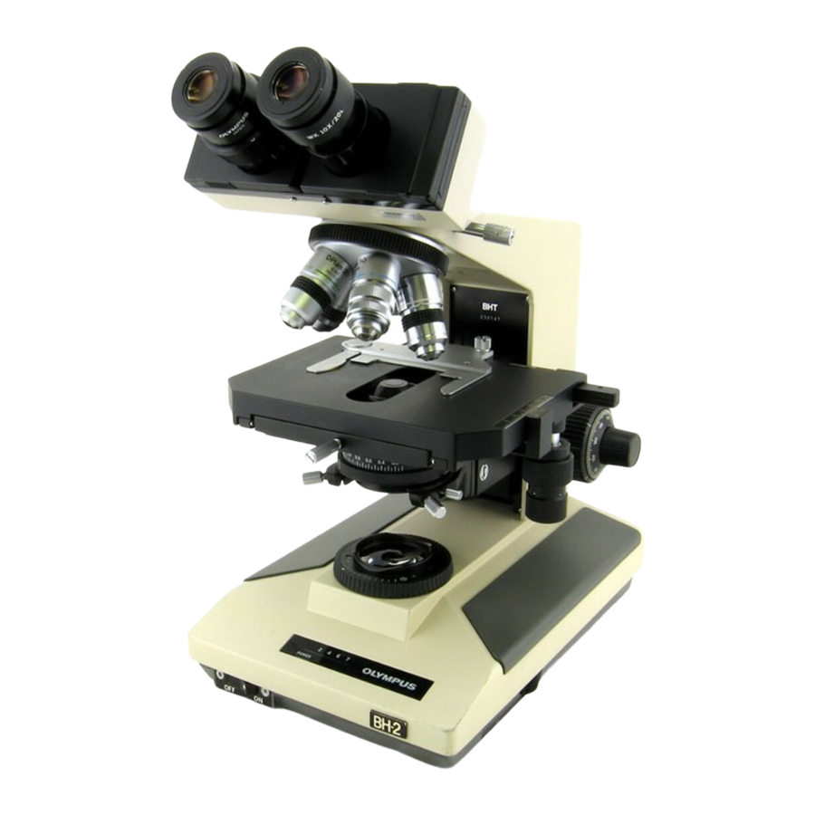
Teardown, Cleaning, and Reassembly of the Miscellaneous Parts of the Olympus BH-2 Microscope Frames
Table of Figures
Revision 1
Page 3 of 45