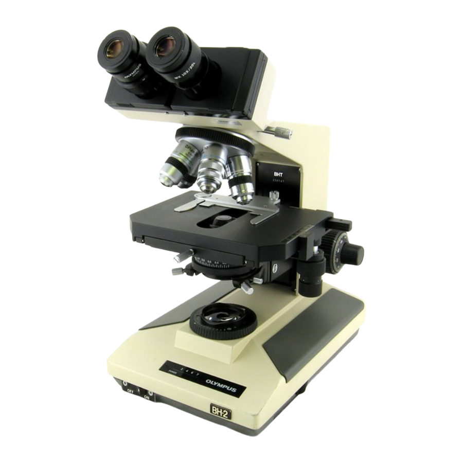
Olympus BH2 Series Teardown, Cleaning And Reassembly - Page 3
Browse online or download pdf Teardown, Cleaning And Reassembly for Microscope Olympus BH2 Series. Olympus BH2 Series 45 pages. Phase contrast
Also for Olympus BH2 Series: Troubleshooting & Adjustment Manual (46 pages), Complete Teardown, Cleaning, And Reassembly (23 pages), Complete Teardown, Cleaning, And Reassembly (40 pages), Manual (6 pages), Installation Manual (9 pages)

Clean Components of Light Inlet Assembly (BHT/BHTU) ____________________________________________ 33
Reassemble the Light Inlet Assembly (BHT/BHTU) _________________________________________________ 33
Reinstall Light Inlet Assembly (BHT/BHTU) ______________________________________________________ 35
Light Exit Assembly __________________________________________________________________________ 36
Servicing the Light Exit Assembly ______________________________________________________________ 37
Disassemble the Light Exit Assembly ___________________________________________________________ 37
Clean the Components of Light Exit Assembly ____________________________________________________ 39
Reinstall the Light Exit Assembly Frame onto the Base _____________________________________________ 41
Reassemble the Light Exit Assembly ____________________________________________________________ 41
Collimating the Integral Substage Lighting ________________________________________________________ 43
A Few Words About Dust Protection _____________________________________________________________ 43
Original Olympus Documentation _______________________________________________________________ 44
Olympus Research Microscopes Series BH2 (BHS) Repair Manual ____________________________________ 44
Olympus Research Corporation BH2 Repair ______________________________________________________ 44
How to Contact the Author ____________________________________________________________________ 44
Appendix 1 _________________________________________________________________________________ 45
Parts, Supplies, and Tools Referenced in this Document ___________________________________________ 45
Parts, Supplies, and Tools ____________________________________________________________________ 45
Sources for Parts, Supplies, and Tools __________________________________________________________ 45
Figure 1 - Head of a typical JIS screw ...............................................................................................................................8
Figure 2 - The viewing head locking screw (BHS/BHT) .....................................................................................................9
Figure 3 - The viewing head locking screw (BHSU/BHTU) ................................................................................................9
Figure 4 - Hold the threaded outer barrel stationary ......................................................................................................9
Figure 5 - Loosen and remove the slotted end-screw................................................................................................... 10
Figure 6 - Snug the knurled outer barrel down ............................................................................................................. 10
Figure 7 - Mounting disk from an old binocular head ................................................................................................... 10
Figure 8 - Place mounting disk into dovetail recess ...................................................................................................... 10
Figure 9 - Slide the mounting disk to expose the e-clip ................................................................................................ 10
Figure 10 - Secure mounting disk so the e-clip stays out .............................................................................................. 11
Figure 11 - Where there's a will there's a way .............................................................................................................. 11
Figure 12 - Carefully remove e-clip from the plunger shaft .......................................................................................... 11
Figure 13 - Remove mounting disk from dovetail recess .............................................................................................. 11
Figure 14 - Remove plunger rod from the inner barrel................................................................................................. 11
Figure 15 - Remove spring from stationary inner barrel ............................................................................................... 11
Figure 16 - Unscrew and remove knurled outer barrel................................................................................................. 12
Figure 17 - Clean the outside of stationary inner barrel ............................................................................................... 12
Figure 18 - Clean the bore of the stationary inner barrel ............................................................................................. 12
Figure 19 - Thoroughly clean the plunger rod ............................................................................................................... 12
Figure 20 - Clean threads and bore of the outer barrel ................................................................................................ 12
Figure 21 - Wash the grease from the extension spring ............................................................................................... 12
Figure 22 - Insert spring into the bore of the inner barrel ............................................................................................ 13
Figure 23 - Lightly grease the shaft of the plunger rod ................................................................................................. 13
Figure 24 - Insert plunger into bore of the inner barrel ................................................................................................ 13
Figure 25 - Apply grease to threads of the inner barrel ................................................................................................ 13
Figure 26 - Reinstall the knurled outer barrel ............................................................................................................... 13
Figure 27 - Test the motion of the spring-loaded plunger ............................................................................................ 13
Figure 28 - Place the mounting disk into dovetail recess .............................................................................................. 14
Figure 29 - Slide mounting disk to expose the shaft end .............................................................................................. 14
Figure 30 - Clamp mounting disk to keep shaft exposed .............................................................................................. 14
Teardown, Cleaning, and Reassembly of the Miscellaneous Parts of the Olympus BH-2 Microscope Frames
Table of Figures
Revision 1
Page 3 of 45
