Olympus BH-NRE 매뉴얼 - 페이지 7
{카테고리_이름} Olympus BH-NRE에 대한 매뉴얼을 온라인으로 검색하거나 PDF를 다운로드하세요. Olympus BH-NRE 17 페이지. Modular revolving nosepiece
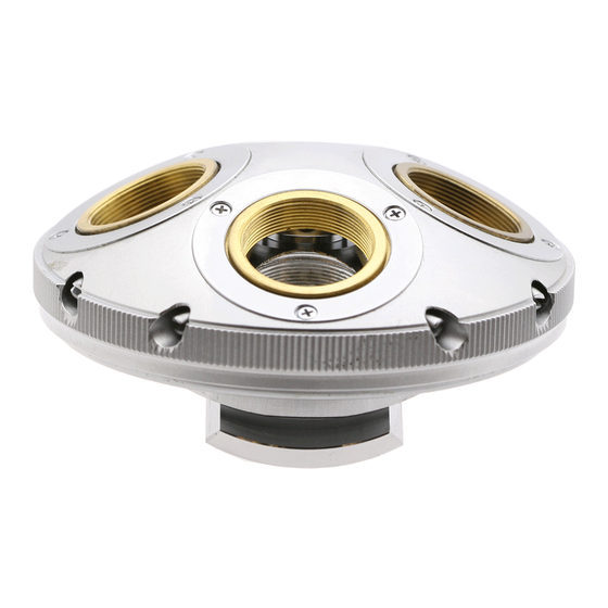
Figure 9 – Remove the screws securing the detent stop
Remove the loose mechanical detent stop from the
stationary base (see
Figure
Figure 10 – Remove the mechanical detent stop
Remove Lock Ring for the Pivot-Adjustment Screw
The slotted lock ring for the pivot-adjustment screw can
be difficult to remove unless the proper tool is used. Do
not attempt to remove the slotted lock ring and pivot-
adjustment screw unless you have access to such a tool,
since the slot in the lock ring will likely be damaged if
you use an improper tool, making removal of the lock
ring much more difficult
A suitable tool for this task can be easily made by filing
or grinding a relief notch for the pivot-adjustment screw
in the center of the blade of a large slotted screwdriver,
as shown in
Figure
11. Note that if you decide to make
such a tool, be sure that the tip of the screwdriver you
select has a blade width matching the outer diameter of
the slotted lock ring, and that the thickness of the blade
is such that it will seat fully into the slot of the slotted
lock ring.
1
Don't even think about using a pair of needle-nose pliers to loosen
the slotted lock ring. It will end badly if you do this. Don't ask me
how I know this.
Complete Teardown, Cleaning, and Reassembly of the Olympus BH-NRE Modular Revolving Nosepiece
10).
1
.
Figure 11 – Screwdriver modified to remove slotted lock ring
Prevent the Revolving Turret from Spinning
Before attempting to loosen the slotted lock ring, the
revolving turret must first be locked in position relative
to the stationary base, to allow for sufficient torque to
be applied to the slotted lock ring to loosen and remove
it. To lock the revolving turret, first spin the revolving
turret until the bore in the stationary base aligns with
one of the four threaded objective bores in the
revolving turret. Next, insert a small screwdriver handle
of the appropriate size into the two bores (see
12). This will prevent the revolving turret from moving
relative to the stationary base when torque is applied to
loosen the slotted lock ring, without causing any
damage to the fragile brass threads in the revolving
turret.
Figure 12 – Insert screwdriver into bores to lock turret
Loosen and Remove the Slotted Lock Ring
Hold the turret assembly by grasping the knurled ring
on the outer perimeter of the revolving turret and use
the slotted screwdriver with the notched tip (see
11) to loosen the slotted lock ring securing the pivot-
adjustment screw to the stationary base (see
Figure
Figure
Figure
13).
Page 7 of 17
Revision 3