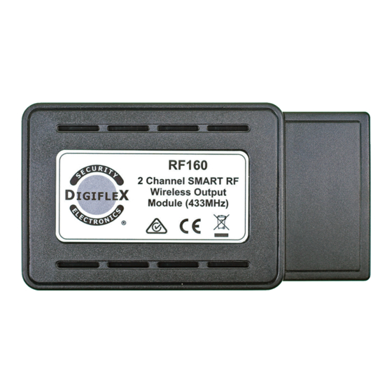
Digiflex RF160 설치 관리자 참조 설명서 - 페이지 4
{카테고리_이름} Digiflex RF160에 대한 설치 관리자 참조 설명서을 온라인으로 검색하거나 PDF를 다운로드하세요. Digiflex RF160 8 페이지. 2 channel smart rf wireless output module - 433mhz

Test RF Device
Outputs > RF Output
Test RF Device
This menu allows the installer to test RF160 module
output for signal level.
1) Press [MENU] + [4] + [3] + [2] and use the up and
down arrows to highlight the output in the list,
then press [OK].
Op1 External Siren
Op2 Strobe Light
Op3 Smoke Sensor PWR
Press
2) The keypad will display the current RF160 ID.
Op6 Garage Door
Waiting for Trigger!
Press OK or MENU
3) Press and hold both relay buttons on the RF160
module to transmit a packet (signal).
Op6 Garage Door
Rx3 Packets=001 v2.02
Signal Good <247>
Press OK or MENU
4) Press [OK] or press [MENU] to exit.
The keypad will display the receiver address that re-
ceived the packet (signal) from the RF160, the packet
count, the firmware of the RF160 and the signal strength.
Receiver LED Indicators
The RF160 2 Channel SMART RF Wireless Output Module includes RED and GREEN LED indicators which provide
visual feedback during system operation. See Table 3 for information on the indicator colours and meanings.
Lable
LED Colour
RLY1
Red
RLY2
Red
RF
Green
PGM
Red
Page
4
P/N: RF160IRG Rev 1.0
MENU 4-3-2
OK or MENU
Purpose
RLY1 Operation /
Programing
RLY2 Operation /
Programing
Packet Receive /
Transmit / Power
Programing Mode
Table 3: RF160 Device LED's
Devices > RF Devices
RF Site Key
This menu allows the installer to set the site key to lock
Digiflex Smart RF sensors to the control panel.
The RF Site Key has been added to lock Smart RF devices
to a specific site. Once a device is registered to a site, it is
locked to the RF Site ID and cannot be learned or operated
on any other site.
To relearn a device onto a different site with a different
RF Site ID, you must first remove power or the battery to
reset the RF device, and it will then learn to any new site.
The factory default RF site key is the serial number of the
control panel. When upgrading panel firmware the RF
Site ID is not changed and will need to be programmed
if required.
LED Indicators
Turns on when the relay is operated.
Turns on when the relay is operated.
Indicates power on the module and receive/transmit data packets.
Blinks each time the system is polled by the control panel.
Meaning
E&OE
MENU 6-2-9
Copyright © 2021
