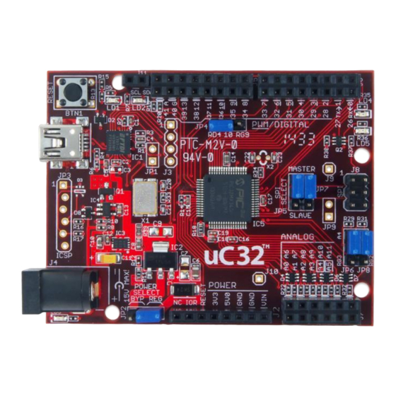
Digilent chipKIT uC32 참조 매뉴얼 - 페이지 6
{카테고리_이름} Digilent chipKIT uC32에 대한 참조 매뉴얼을 온라인으로 검색하거나 PDF를 다운로드하세요. Digilent chipKIT uC32 18 페이지.

chipKIT™ uC32™ Board Reference Manual
3
chipKIT uC32 Hardware Description
3.1
MPIDE and USB Serial Communications
The uC32 board is designed to be used with the Multi-Platform IDE (MPIDE). MPIDE is a modified version of the
Arduino IDE that supports the PIC32 microprocessors and is backwards-compatible with the Arduino IDE. The
MPIDE uses a serial communications port to communicate with a boot loader running on the uC32 board. The
serial port on the uC32 board is implemented using an FTDI FT232R USB serial converter. Before attempting to use
the MPIDE to communicate with the uC32, the appropriate USB device driver must be installed.
The uC32 board uses a standard mini-USB connector for connection to a USB port on the PC. When the MPIDE
needs to communicate with the uC32 board, the board is reset and starts running the boot loader. The MPIDE then
establishes communications with the boot loader and downloads the program to the board.
When the MPIDE opens the serial communications connection on the PC, the DTR pin on the FT232R chip is driven
low. This pin is coupled through a capacitor to the MCLR pin on the PIC32 microcontroller. Driving the MCLR line
low resets the microcontroller, restarting execution with the boot loader.
This automatic reset action (when the serial communications connection is opened) can be disabled. To disable
this operation, there is a cuttable trace on the bottom of the board between the pins on JP1. JP1 is normally not
loaded. If the trace between the pins on JP1 has been cut, the automatic reset operation can be restored by
loading JP1 and inserting a shorting block across it.
Two red LEDs (LD1 and LD2) will blink when data is being sent or received between the uC32 and the PC over the
serial connection.
The header connector J3 provides access to the other serial handshaking signals provided by the FT232R.
Connector J3 is not loaded at the factory and can be installed by the user to access these signals.
3.2
Power Supply
The uC32 is designed to be powered either via USB or from an external power supply. There is an automatic
switch-over circuit that causes the external supply to be used if both supplies are present.
The power supply section in the uC32 uses two voltage regulators. The first regulates the external voltage to 5V to
power the VCC5V0 bus. The second regulates the VCC5V0 bus to 3.3V to provide power to the VCC3V3 bus that
powers the PIC32 microcontroller.
The 5V voltage regulator is normally an NCP1117. The board is designed to be able to also use an LM1117, but the
NCP1117 is the part normally used. The NCP1117 is rated for an output current of 1A (the LM1117 is rated for
800mA). The dropout voltage of the NCP1117 is a maximum of 1.2V at the rated output current (1.3V for the
LM1117).
There is a reverse polarity protection diode in the external power supply circuit. Considering the diode drop plus
the forward drop across the regulator, the minimum input voltage to the regulator should be 7V to produce a
reliable 5V output. The absolute maximum input voltage of both the NCP1117 and the LM1117 is 20V. The
recommended maximum operating voltage is 15V.
Copyright Digilent, Inc. All rights reserved.
Other product and company names mentioned may be trademarks of their respective owners.
Page 6 of 17
