Bitron Video MVC3000 사용 설명서 - 페이지 8
{카테고리_이름} Bitron Video MVC3000에 대한 사용 설명서을 온라인으로 검색하거나 PDF를 다운로드하세요. Bitron Video MVC3000 8 페이지.
In case two monitors have been programmed with the same code, both of them will ring at the same time when their code is
called by the TDE3000.
In case one wants to connect more than one monitors with same the code, it will be necessary to refer to the manual of
TDE3000, where there are particular installation descriptions and possible limitations.
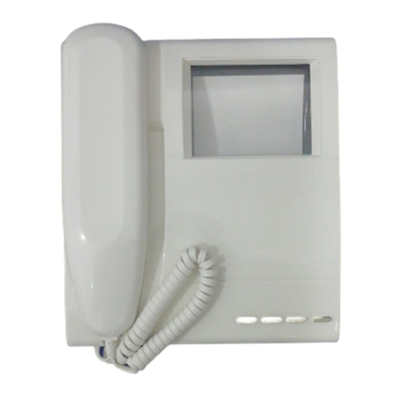
COMMANDS AND SETTINGS
[ See. Fig.6 ]
The following describes the commands and possible settings of the monitor (all versions).
DOOR-OPENING PUSH BUTTON
1)
Its activation opens the door. A call must be received in order to open the door from the monitor if the conversation
privacy function is provided.
2)
SELF START PUSH BUTTON
Press the button to activate the camera and turn the monitor on (if it has been connected to the "E" wire)
BUTTONS (2) FOR AUXILIARY SERVICES
3)
If properly connected, they are used to activate other device such as stairs light, electric gates, auxiliary cameras, etc.
Remember that the two buttons have the Q contact as a common pole.
4)
CONTRAST ADJUSTEMENT
Use it to set the b/w picture contrast, or the colour saturation in the MVC3000 model
5)
BRIGHTNESS SETTING
Set the average brightness of the picture.
ELECTRONIC CALL VOLUME ADJUSTMENT
6)
Permits three ringing levels ( high - medium - low )
HOOK LEVER
7)
Automatically operated by picking up and hanging up the handset, it activates and disables the speech function.
NOTE: With DOMULAR 3000 visitor panels the self-start function can be operated
only when another monitor is on.
HANDLING AND CARE
Do not store in warm or cold places. Extreme temperatures ( warm or cold) can shorten the life of electronic
systems and can also stain or melt some plastic parts or cause malfunctioning. Important: keep away from
frost.
Do not use or store in very dirty or dusty places. The electronics can be damaged. The mobile parts can
rapidly wear out.
If dropped, it may not work anymore. The printed circuits may break and the external plastic could not
survive the impact
Do not use chemicals or strong solvents to clean it. Use only a wet duster once in a while. Avoid rough
wiping so as not to scratch the surfaces.
13
TROUBLESHOOTING
This section is useful for identifying electrical and mechanical problems occurring in a typical installation, that is with one
visitor panel, one A70 power unit and one or more monitors connected to a column.
Check the following before assuming you have a fault:
Problem
Possible cause
The monitor does not switch
Wires incorrectly positioned in the
on.
terminal board.
Incorrectly positioned configuration
jumpers.
Dull colours (MVC) or
Wires A or B not connected.
snow-effect (MV).
Door panel too far away from
monitor.
Incorrect positioning of selector L/H
on back of monitor.
No picture on monitor.
No video signal connection.
The picture on the monitor
Wire A and B are inverted.
is distorted with a black
dominant.
The picture on the monitor
Incorrect positioning of rear
is blurred or slightly
potentiometer shown in fig. 5C.
distorted.
MV-MVC3000: in BUS
Incorrect positioning of micro
systems, the monitor does
switch.
not ring and does not switch
on.
In traditional systems: the
Incorrect connection or positioning
monitor does not ring and
of jumper J1
does not switch on.
In traditional systems: no
Conversation privacy function is on.
audio is present and the
door cannot be opened.
MV-MVC1000: audio
Interference picked up in the
interference during floor
system.
calls by another user.
Audio interference is picked
Interference picked up in the
up in normal conditions.
system.
The door is not opened
Cross-section area of the wires in
when the specific button on
the system is not appropriate.
the monitor is pressed.
Faulty door opener button on the
monitor.
The monitor does not switch
A call is in progress in the system.
on when the self-start button
is pressed.
Wire E of the monitor is not
connected.
Solution
Check operation of the system.
Check that the jumpers are positioned according to the default
configuration.
Use a multimeter to run the following tests:
1) Presence of call signal on terminal board wire C by arranging
the probes between terminals C and 1. Check that during the call, a
negative voltage of approximately 8 volts is present on terminal 1.
2) Presence of monitor power between terminal board wires 1 and
3 by arranging the probes between terminals 1 and 3. Check that
after the call a positive voltage of approximately 17/20 volts is
present.
Check connection and perfect it, if necessary. If improvement is not
possible, check the wires in the system.
Adjust the potentiometer shown in fig. 5C to obtain a sharp picture or
bright colours. If the problem persists, use a AMV3000 - code
AV3007 video amplifier.
In systems with SD55 video distributor, the selector must be set to
"L."
In entry/exit systems, if must be set to "H".
Connect wires A and B on the terminal board.
Connect wires A and B of the monitor correctly.
Turn the potentiometer anticlockwise in fig. 5C using a slot
screwdriver to decrease the effect.
Check positioning of jumper J1. Check call codes and position them
correctly.
Check wires in system and position of jumper J1 (between 1 and 2).
This is normal in systems with conversation privacy function. In other
systems, check the position of the jumper J2 (between 1 and 2).
Floor calls can generate audio interference. Keep the floor call wire
as separated as possible from the system wire.
Check that the wires are separated from the mains power lines.
Check correct operation of electronic devices near the monitor or
the external unit.
Refer to the table in the video manual showing the system wire
dimensions.
If the system is working perfectly but a monitor cannot open the door,
check operation of the door opener button (using a multimeter): pins
1 and C of the monitor must be short-circuited when the door opener
button is pressed.
Wait for the end of the call in progress and try again.
Connect wire E between the monitor and the external audio-video
unit.
14