Siemens SINAMICS G120 간결한 사용 설명서 - 페이지 27

{카테고리_이름} Siemens SINAMICS G120에 대한 간결한 사용 설명서을 온라인으로 검색하거나 PDF를 다운로드하세요. Siemens SINAMICS G120 32 페이지. Using blocksize converters in marine applications
Siemens SINAMICS G120에 대해서도 마찬가지입니다: 시작하기 (46 페이지), 사용 설명서 (32 페이지), 시작하기 (30 페이지), 하드웨어 설치 지침 (2 페이지), 설치 지침 및 사용 설명서 (2 페이지), 설치 지침 (2 페이지), 설치 지침 (2 페이지), 매뉴얼 (42 페이지), 시작하기 (50 페이지), 장치 설명서 (34 페이지), 빠른 설치 매뉴얼 (2 페이지), 애플리케이션 설명 (50 페이지), 간결한 사용 설명서 (2 페이지), 매뉴얼 (31 페이지), 애플리케이션 매뉴얼 (34 페이지), 간결한 사용 설명서 (2 페이지), 간결한 사용 설명서 (2 페이지)
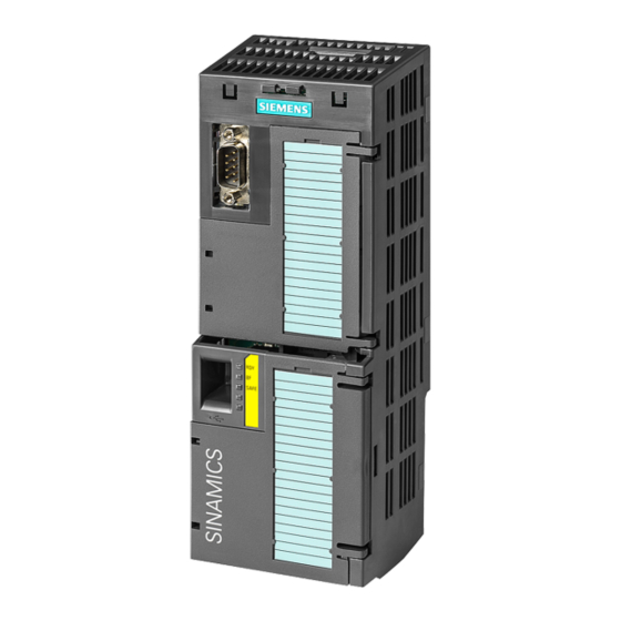
Siemens SINAMICS G120 간결한 사용 설명서
Examples for telegrams via PROFIBUS and PROFINET
Telegram 1:
Control word 1 (STW1), PZD receive word 1 (word: r2050[0], bits: r2090.00 ... r2090.15)
Bit
Meaning
0
0 = OFF1
0 → 1 = ON
1
0 = OFF2
1 = No OFF2
2
0 = Quick stop (OFF3)
1 = No quick stop (OFF3)
3
0 = Inhibit operation
1 = Enable operation
4
0 = Disable RFG
1 = Do not disable RFG
5
0 = Stop RFG
1 = Enable RFG
6
0 = Inhibit setpoint
1 = Enable setpoint
7
0 → 1 = Acknowledge faults
8, 9
Reserved
10
0 = No control via PLC
1 = Control via PLC
11
1 = Direction reversal
12
Not used
13
1 = MOP up
14
1 = MOP down
15
Reserved
CU240B-2 and CU240E-2 Control Units
Compact Operating Instructions, 04/2015, A5E35792002B AA
Explanation
The motor brakes with the ramp-down time p1121 of the ramp-function generator.
The inverter switches off the motor at standstill.
The inverter goes into the "ready" state. If, in addition bit 3 = 1, then the inverter
switches on the motor.
Switch off the motor immediately, the motor then coasts down to a standstill.
Precondition in order to be able to switch on the motor using bit 0 (ON command).
The motor brakes with the OFF3 ramp-down time p1135 down to standstill.
Precondition in order to be able to switch on the motor using bit 0 (ON command).
Switch off the motor immediately → motor coasts down to a standstill.
Precondition in order to be able to switch on the motor using bit 0 (ON command).
The inverter immediately sets its ramp-function generator output to 0.
The ramp-function generator can be enabled.
The output of the ramp-function generator stops at the actual value.
The output of the ramp-function generator follows the setpoint.
The inverter brakes the motor with the ramp-down time p1121 of the ramp-function
generator.
Motor accelerates with the ramp-up time p1120 to the setpoint.
Acknowledge fault. If the ON command is still active (bit 0 = 1), the inverter
switches to "closing lockout" state.
The inverter ignores the process data from the fieldbus.
Control via fieldbus, the inverter accepts the process data from the fieldbus.
Invert setpoint in the inverter.
Increase the setpoint saved in the motorized potentiometer.
Reduce the setpoint saved in the motorized potentiometer.
Changes over between settings for different operation interfaces (command data
sets).
4.3 Connecting the inverter to the fieldbus
STW1
Control word 1
ZSW1
Status word 1
PZD01/02
Process data 16-bit
NSOLL_A
Speed setpoint
NIST_A
Speed actual value
Commissioning
27