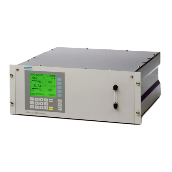
Siemens ULTRAMAT 6F 사용 설명서 - 페이지 31
{카테고리_이름} Siemens ULTRAMAT 6F에 대한 사용 설명서을 온라인으로 검색하거나 PDF를 다운로드하세요. Siemens ULTRAMAT 6F 49 페이지. Gas analyzer for the determination of ir-absorbing gases
Siemens ULTRAMAT 6F에 대해서도 마찬가지입니다: 추가 장비 매뉴얼 (20 페이지), 안전 매뉴얼 (24 페이지)

5.2.2
Recommended test setup of ULTRAMAT 6F
BI
Blanking plug
2
Outlet of sample gas path
4
Outlet of reference gas path
Figure 5-2
Test setup for the leak test of the sample gas path and the flow-type reference gas path (dashed line) of the
ULTRAMAT 6F
Install the test setup as follows:
1. Close the sample gas inlet
2. Install a suitable shutoff valve (e.g. needle valve V1) of sufficient tightness into the sample gas line downstream of the
②
sample gas outlet
3. Connect a pressure regulator with a measuring range of 50 kPa and a resolution of 0.1 kPa downstream of shutoff valve
V1.
4. Proceed accordingly if the analyzer has a flow-type reference gas connection (
③
gas inlet
and install the test setup downstream of the reference gas outlet ④.
5.2.3
Carrying out the leak test
Proceed as follows:
1. Carefully open the needle valve. A pressure is then built up in the containment system.
2. Once the test pressure has been reached (see following table), close the needle valve again.
3. Wait approx. 5 minutes. Thermal compensation is carried out in the analyzer during this time. The temperature of the
sample gas path must not change during the test!
4. Now determine the pressure change Δp during an additional 5 minute period.
The gas path is sufficiently leak-tight if the pressure change Δp in 5 minutes is less than the test value listed in the
following table.
OXYMAT 6F
CALOMAT 6F
CALOMAT 62F
ULTRAMAT 6F
*) The test values have been defined under the assumption that the maximum volume between the shutoff units (valves) and
the containment system is 10 ml. This corresponds to a pipe with an inside diameter of 4 mm and a length of ap-
prox. 80 cm.
Compact Operating Instructions in accordance with EN 61010-1 and EN 60079-0
A5E45779389002-01, 09/2018
①
using a blanking plug.
.
Test pressure 200 kPa (2.0 bar) (rel.)
Test pressure 50 kPa (0.5 bar) (rel.)
Test pressure 10 kPa (0.1 bar) (rel.)
Test pressure 50 kPa (0.5 bar) (rel.)
M
Manometer (gauge pressure)
DR
Pressure regulator
V1
Shut-off valve (leak rate < 10
③
④
,
Test value *) Δp = 3 hPa (mbar)
Test value *) Δp = 6 hPa (mbar)
Test value *) Δp = 9.5 hPa (mbar)
Test value *) Δp = 2 hPa (mbar)
kPa*l/s)
-6
, dashed line). Close the reference
31
