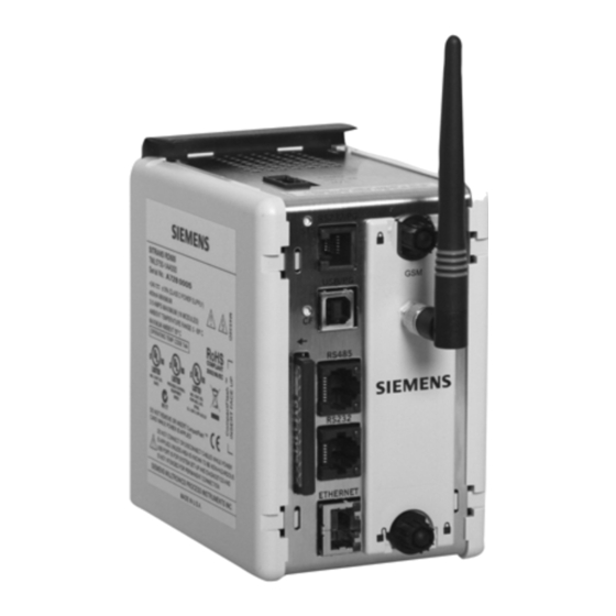
Siemens SITRANS RD500 사용 설명서 - 페이지 4
{카테고리_이름} Siemens SITRANS RD500에 대한 사용 설명서을 온라인으로 검색하거나 PDF를 다운로드하세요. Siemens SITRANS RD500 8 페이지. Configuring sitrans rd500 for connection to multiranger with modbus rtu
Siemens SITRANS RD500에 대해서도 마찬가지입니다: 사용 설명서 (48 페이지), 사용 설명서 (8 페이지), 사용 설명서 (8 페이지), 애플리케이션 매뉴얼 (6 페이지), 매뉴얼 (11 페이지), 적용 사례 (9 페이지)

GENERAL SPECIFICATIONS (CONT'D)
3. MEMORY: Non-volatile memory retains all programmable parameters. RD500
also stores the parameters in order to reprogram modules that are replaced.
4. ISOLATION LEVEL: 500 Vrms @ 50/60 Hz for 1 minute between the Signal Inputs
and the RD500 Power Supply Input.
5. COMMUNICATIONS: Provided by the RD500
6. CERTIFICATIONS AND COMPLIANCES:
SAFETY
UL508, CSA C22.2 No. 14-M05, UL61010-1, CAN/CSA C22.2 No. 61010-1 and
ANSI/ISA 12.12.01-2007, CSA 22.2 No. 213-M1987
LISTED by Und. Lab. Inc. to U.S. and Canadian safety standards
IEC 61010-1, EN 61010-1: Safety requirements for electrical equipment for
measurement, control, and laboratory use, Part 1.
ELECTROMAGNETIC COMPATIBILITY
Emissions and Immunity to EN 61326: 2006: Electrical Equipment for
Measurement, Control and Laboratory use.
Electrostatic discharge
EN 61000-4-2
Electromagnetic RF fields
EN 61000-4-3
Fast transients (burst)
EN 61000-4-4
Surge
EN 61000-4-5
RF conducted interference
EN 61000-4-6
Emissions:
Emissions
EN 55011
Notes:
1. Criterion A: Normal operation within specified limits.
2. Criterion B: Temporary loss of performance from which the unit self-
recovers.
3. The module's analog input and/or output signals may deviate during
disturbance, but self-recover when disturbance is removed.
4. Power supplied from backplane via RD500 Module.
7. ENVIRONMENTAL CONDITIONS:
Operating Temperature Range: 0 to +50 °C
Storage Temperature Range: -40 to +85 °C
Operating and Storage Humidity: 85% max relative humidity, non-condensing,
from 0 to +50 °C
7ML19985MB01
Criterion B
4 kV contact discharge
8 kV air discharge
3
Criterion B
10 V/m
Criterion B
power
2 kV
signal
1 kV
Criterion B
power
1 kV L-L, 2 kV L-G
signal
1 kV
Criterion A
3 V/rms
Class A
BLOCK DIAGRAM
PORT 1
PROGRAMMING
A
PORT 2
COMMUNICATIONS
A
POWER
+
24VDC
SUPPLY
-
A
ISOLATED
PORT 3
ETHERNET
B
RD500
SITRANS RD500
Vibration According to IEC 68-2-6: Operational 10 to 150 Hz, 0.075 mm
amplitude in X, Y, Z direction 1 g.
Shock According to IEC 68-2-27: Operational 25 g's, 11 msec in 3 directions.
Altitude: Up to 2000 meters
8. CONSTRUCTION: Case body is high impact plastic. For indoor use only.
Installation Category II, Pollution Degree 2.
9. CONNECTIONS: Removable wire clamp screw terminal blocks
Wire Gage: 28-16 AWG terminal gage wire
Torque: 1.96-2.23 inch/lbs (0.22-0.25 N-m)
10. MOUNTING: Snaps on to standard DIN style top hat (T) profile mounting rails
according to EN50022 -35 x 7.5 and -35 x 15.
11. WEIGHT: 6 oz (170.1 g)
12. INPUTS:
Channels: 8 single-ended
Ranges: 0-20 mA or 4-20 mA
Effective Resolution: Full 16-bit
Programmable Scaling: ±30,000
Sample Time: 50 msec - 400 msec, depending on number of enabled inputs.
ENABLED
SCAN TIME
INPUTS
(READING RATE)
1
50 msec (20 Hz)
2
100 msec (10 Hz)
3
150 msec (6.7 Hz)
4
200 msec (5 Hz)
5
250 msec (4 Hz)
6
300 msec (3.3 Hz)
7
350 msec (2.9 Hz)
8
400 msec (2.5 Hz)
Common Mode Rejection: >110 dB, 50/60 Hz
Normal Mode Rejection: >90 dB, 50/60 Hz
Step Response Time: One scan time (to within 99% of final value)
Input Impedance: 10
Max. Continuous Overload: 100 mA
13. ACCURACY: ±0.1% of span
14. INPUT FAULT RESPONSE: Upscale Drive, Input Fault Alarm bit set high, ALM
LED illuminates below -3 mA, and above 23 mA for 0-20 mA range; below +3
mA and above 23 mA for 4-20 mA signals.
WARNING - EXPLOSION HAZARD - DO NOT DISCONNECT
EQUIPMENT UNLESS POWER HAS BEEN SWITCHED OFF OR
HAZARDOUS CONDITIONS ARE NOT PRESENT.
ISOLATED
INPUTS
C
POWER
SUPPLY
Module
Page 2
